Figures & data
Figure 1:1 Specially designed insertion instrument for application of tantalum markers.
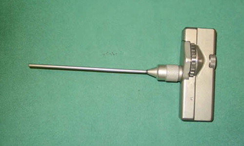
Figure 1:2 Posterior placing of tantalum indicators in the two transverse processes and in the spinous process to create a three-dimensional rigid body for radiostereometry.
Figure 1:3 Additional tantalum indicators applied in the ventral parts of the vertebra during anterior fusion in order to enlarge the rigid body for radiostereometry.
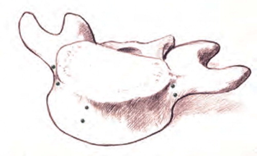
Figure 1:4A RSA in supine, baseline position. (Reproduced with permission from Spine).
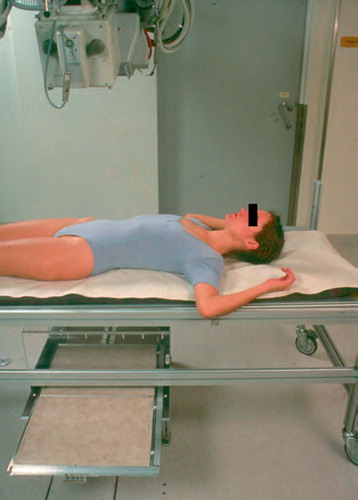
Figure 1:4B RSA in normal standing position in a stabilizing frame with no weightsharing on the arms. (Reproduced with permission from Spine).
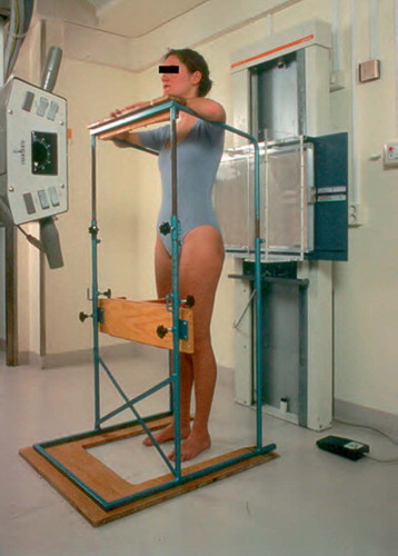
Figure 1:4C RSA in sitting position on a chair with standardized lowering of the knees allowing free passage of the x-rays above the femoral shafts to the lumbosacral spine. (Reproduced with permission from Spine).
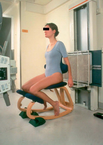
Figure 1:4D RSA in standing position with sandbags weighing in total 20 kilograms equally distributed on both shoulders. (Reproduced with permission from Spine).
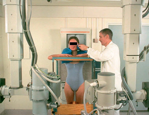
Figure 1:5A Mean mobility along the sagittal axis over the lower 3 lumbar segments in 12 patients, investigated in 3 standardized positions of provocation.
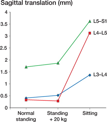
Figure 1:5B Mean mobility along the vertical axis over the lower 3 lumbar segments in 12 patients, investigated in 3 standardized positions of provocation.
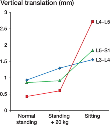
Table 2 :1. Intervertebral translations (mm) over 25 normal discs
Table 2 :2. Intervertebral translations (mm) over 36 discs ordered according to the grade of degeneration
Figure 2:1 Mean vertical intervertebral mobility with confidence intervals given for 36 discs categorized according to the grade of degeneration. (Reproduced with permission from Eur Spine J).
Figure 2:2 Mean sagittal intervertebral mobility with confidence intervals given for 36 discs categorized according to the grade of degeneration. (Reproduced with permission from Eur Spine J).
Figure 2:3 A. Spondylolysis and grade I olisthesis in a 46-year-old man having low back pain for one year. B. MRI reveals degenerative findings of the disc under the slipped vertebra with disc height reduction, dehydration and endplate reaction.
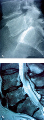
Figure 2:4 Lumbosacral sagittal mobility in eight patients with spondylolysis and low back pain compared in matched pairs with the mobility of patients without spondylolysis having low back pain on degenerative basis. The grade of disc degeneration is categorized and given on the x-axis for each pair. (Reproduced with permission from Spine).
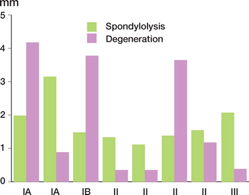
Figure 3:1 The Magerl frame for external spinal fixation.
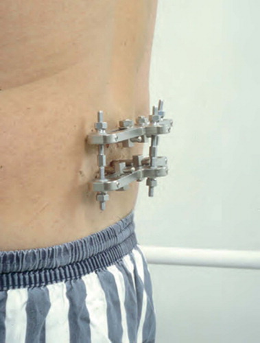
Figure 3:2 Tantalum indicators for radiostereometry implanted into the bases of the two transverse processes of the spondylolytic fifth vertebra and in the lateral masses and the central portion of the sacrum. Two pedicular screws are placed on each level. A. Anteroposterior view. B. Lateral vew. (Reproduced with permission from Spine).
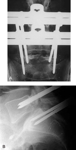
Figure 3:3 Sagittal intervertebral translations for seven patients measured both with the external frame loosened and with the frame fixed. The dotted line indicates the accuracy for sagittal translation, 0.7 mm. (Reproduced with permission from Spine).
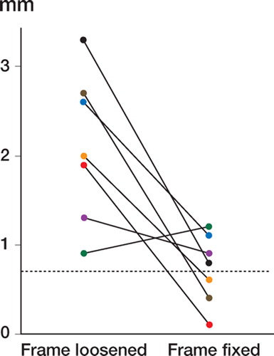
Table 3 :1. Clinical data and RSA intervertebral translations in 7 patients without fixator (left columns), with external fixator fixed (middle columns) and loosened (right columns)
Figure 4:1 Uninstrumented fusion with solid bony bridging between the transverse processes of the L4 and L5 vertebra. A. Anteroposterior view. B. Lateral view.
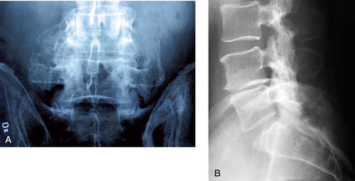
Figure 4:2 Schematic drawing of posterolateral uninstrumented fusion after decortication but before bone harvesting with a reamer.
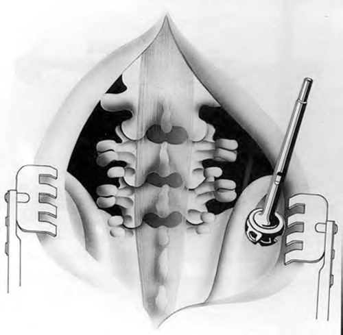
Figure 4:3 Mean sagittal translation determined by radiostereometry in 8 solidly healing uninstrumented fusions. The dotted line indicates the accuracy for sagittal translation, 0.7 mm.
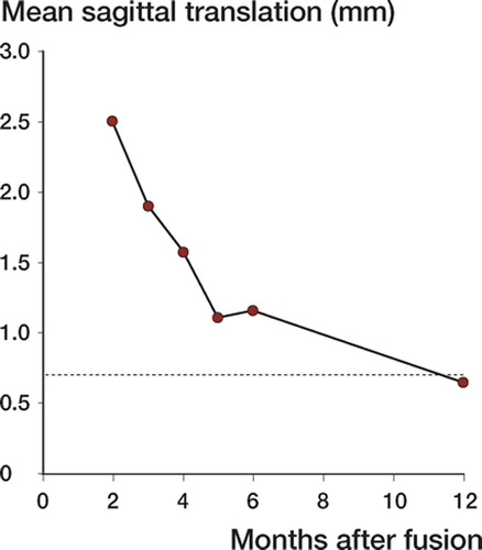
Figure 4:4 Mean vertical translation determined by radiostereometry in 8 solidly healing uninstrumented fusions. The dotted line indicates the accuracy for vertical translation, 0.6 mm.
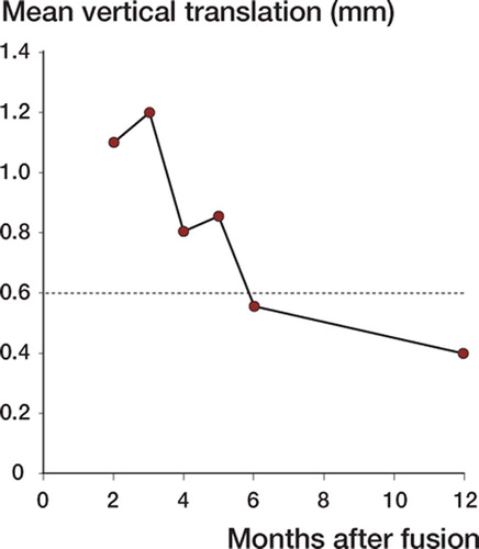
Table 4 :1 Mobility schedule over time for 11 patients with uninstrumented fusion
Figure 5:1 Instrumented fusion L4–L5 with bridging trabecular bone between transverse processes lateral to VSP implants. A. Anteroposterior view. B. Lateral vew.
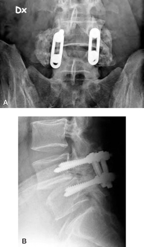
Figure 6:1 Instrumented fusion L4–L5 with bridging trabecular bone between transverse processes lateral to Diapason implants. A. Anteroposterior view. B. Lateral vew.
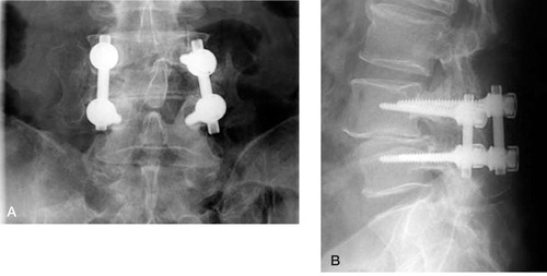
Table 6. 1. Intervertebral translations (mm) 4 weeks after fusion for all operated segments
Figure 8:1 Patient number 1. Conventional radiography showing no reaction around the implant at one year follow-up. Tantalum indicators both in the ventral and dorsal parts of the vertebrae fused. A. Anteroposterior view. B. Lateral view.
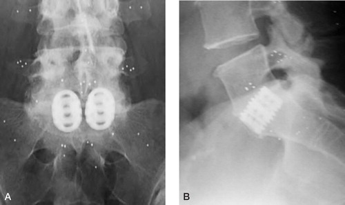
Table 8 :1. Intervertebral mobility (mm) before and through the postoperative course after anterior fusion
Figure 9:1 Posterolateral fusion after decortication and deposition of BMP-7. No bone grafting performed. A. Anteroposterior view. B. Lateral view.
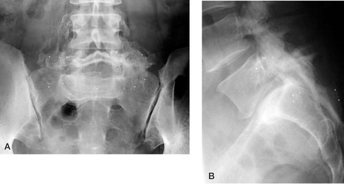
Figure 10:1 Molded, rigid lumbar orthosis made of light weight material. A. Anteroposterior view. B. Lateral view. (Reproduced with permission from J Spinal Disord).
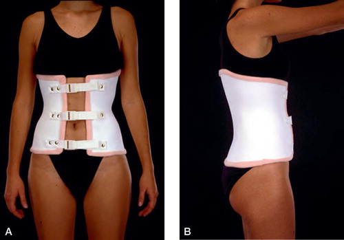
Figure 10:2 Lumbar canvas corset with molded plastic posterior support. A. Anteroposterior view. B. Lateral vew. (Reproduced with permission from J Spinal Disord).
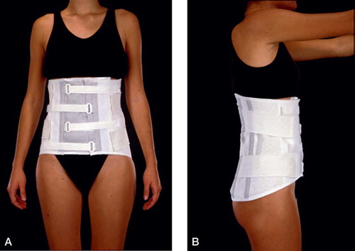
Table 10 :1. Clinical data and RSA intervertebral translations of 7 patients with different lumbar support
Figure 10:3 Molded, rigid lumbar orthosis made of light weight material extended to one thigh immobilizing one hip. A. Anteroposterior view. B. Lateral vew. (Reproduced with permission from Spine).
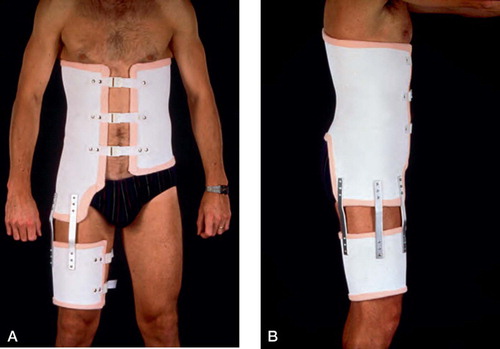
Table 10 :2. Clinical data and RSA intervertebral translations of 9 patients with and without orthosis with unilateral hip immobilization
Figure 11:1 A. Computerized tomography in a patient with relapsing leg pain 12 years after decompression and fusion L4–S1. B. MRI of the same patient reveals a significant spinal stenosis of the segment proximal, adjacent to fusion with a small anterior slip of L3.
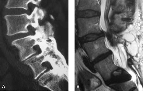
Figure 11:2 Mobility of the L4–L5 and L5–S1 segments for one patient (case 2) representing the pattern with increased mobility of the adjacent segment after fusion. (Reproduced with permission from Spine).
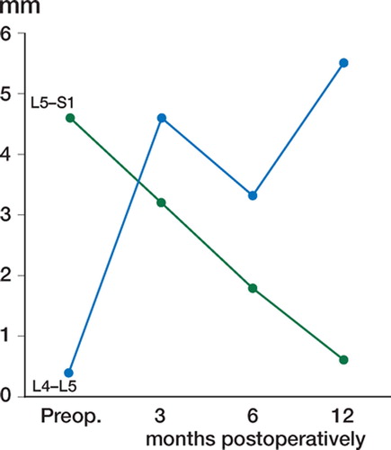
Figure 11:3 Mobility of the L4–L5 and L5–S1 segments for one patient (case 4) representing the pattern with decreased mobility of the adjacent segment after fusion. (Reproduced with permission from Spine).
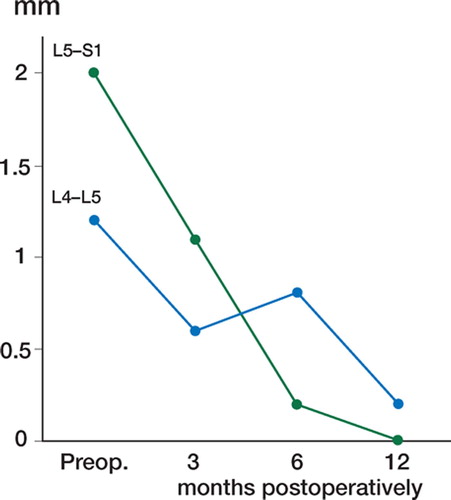
Table 11 :1. RSA intervertebral translations in the adjacent L4–L5 segment for six patients before and after posterolateral lumbosacral fusion