
Figures & data
Figure 1. Schematic of MEPC-based metasurface backward RCS reduction mechanism.
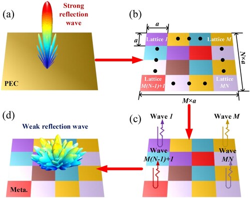
Figure 2. Geometry of the lattice. (d = 8.8 mm, ml = 40.5 mm, mw = 5.5 mm, a = 44 mm, w = 0.4 mm).
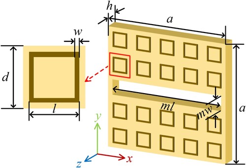
Figure 3. Backscattered fields of the lattices under normal incidence at both polarizations. (a) Amplitude and (b) phase at x-polarization, (c) amplitude and (d) phase at y-polarization.
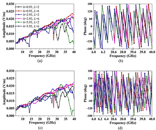
Figure 4. The simulated RCS reduction under normal incidence at dual polarizations.
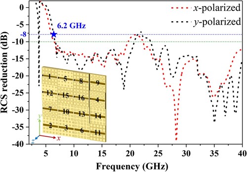
Table 1. The optimized results of 16 lattices (Unit: mm).
Figure 5. Geometry of proposed antenna with metasurface. (The reference antenna doesn’t contain the metasurface)
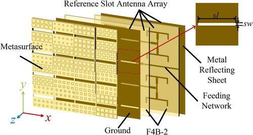
Figure 6. (a) The fabricated reference and (b) proposed slot antenna.
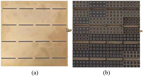
Figure 7. Simulated and measured return loss of the reference and proposed array antenna.
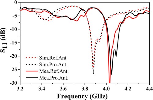
Figure 8. Simulated radiation patterns of both antennas at 3.90 GHz and measured radiation patterns of both antennas at 4.10 GHz. (a) φ = 0° (b) φ = 90°.
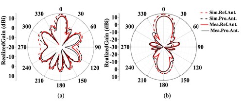
Figure 9. The simulated RCS and measured RCS reduction of the reference antenna and the proposed antenna under normal incidence.
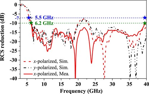
Figure 10. The simulated scattering patterns at 18 GHz on UV coordinates on (a) PEC surface and proposed antenna at (b) x-polarization (c) y-polarization.
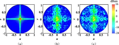
Figure 11. The simulated RCS reduction under oblique incidences for both polarizations. (a) TE-polarization, (b) TM-polarization.
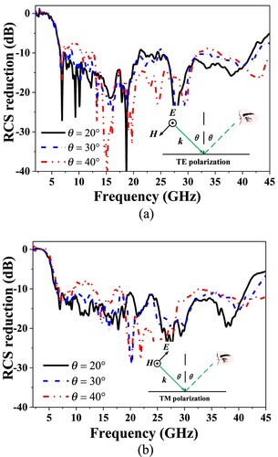
Table 2. Comparison between the proposed slot antenna and previous low-RCS designs.