977
Views
12
CrossRef citations to date
0
Altmetric
Original Articles

Magnetoresistance and electroresistance effects in Fe3O4 nanoparticle system

, , &
Pages 391-397 | Received 19 Jan 2012, Accepted 28 Jan 2012, Published online: 14 May 2012

Figures & data

Figure 1. (Colour online) (a) The XRD pattern of the as prepared Fe3O4 nanoparticles is presented. In the same panel, the JCPDF data (red bars) is also presented for comparison. (b) The TEM image of the Fe3O4 nanoparticles with the inset showing the high-resolution image of a single particle. Panel (c) shows the particle size distribution and the lognormal fitting.
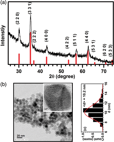
Figure 1. (Colour online) (a) The XRD pattern of the as prepared Fe3O4 nanoparticles is presented. In the same panel, the JCPDF data (red bars) is also presented for comparison. (b) The TEM image of the Fe3O4 nanoparticles with the inset showing the high-resolution image of a single particle. Panel (c) shows the particle size distribution and the lognormal fitting.

Figure 2. (a) The FC and ZFC M(T) data are presented for as prepared Fe3O4 nanoparticles. The cooling and measuring magnetic field is set as 5 mT. Panel (b) shows the hysteresis (M(H)) loops at two different temperatures, 5 and 50 K. The low-field magnetisation data is presented as inset to distinguish the coercive field values.
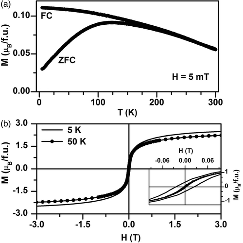
Figure 2. (a) The FC and ZFC M(T) data are presented for as prepared Fe3O4 nanoparticles. The cooling and measuring magnetic field is set as 5 mT. Panel (b) shows the hysteresis (M(H)) loops at two different temperatures, 5 and 50 K. The low-field magnetisation data is presented as inset to distinguish the coercive field values.

Figure 3. The panel (a) shows the hysteresis (M(H)) loops of the annealed pellets of Fe3O4 nanoparticles, at temperatures indicated. Inset shows the variation of coercive field, H C and saturation magnetisation, M S with temperature. In panel (b) the magnetoresistance (MR%) as a function of applied field (H) is plotted, at different temperatures. The inset shows the same plots for larger H-scale. The panel (c) presents the relation between and H C at different temperatures, H C ∼ .
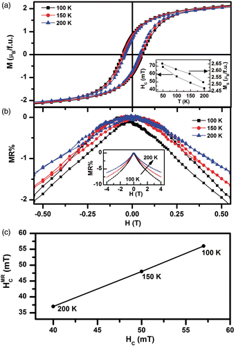
Figure 3. The panel (a) shows the hysteresis (M(H)) loops of the annealed pellets of Fe3O4 nanoparticles, at temperatures indicated. Inset shows the variation of coercive field, H C and saturation magnetisation, M S with temperature. In panel (b) the magnetoresistance (MR%) as a function of applied field (H) is plotted, at different temperatures. The inset shows the same plots for larger H-scale. The panel (c) presents the relation between and H C at different temperatures, H C ∼ .

Figure 4. The resistance (R) as a function of temperature (T) measured with four different excitation currents (50 µA, 100 µA, 1 mA and 10 mA) is plotted. It is to be noted that the data for the first two excitation currents fall on each other. The arrows for the 10 mA curve represent the temperature scanning direction.
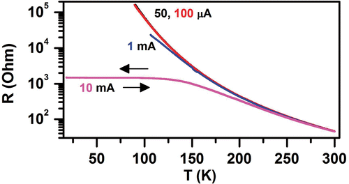
Figure 4. The resistance (R) as a function of temperature (T) measured with four different excitation currents (50 µA, 100 µA, 1 mA and 10 mA) is plotted. It is to be noted that the data for the first two excitation currents fall on each other. The arrows for the 10 mA curve represent the temperature scanning direction.

Reprints and Corporate Permissions

Please note: Selecting permissions does not provide access to the full text of the article, please see our help page How do I view content?

To request a reprint or corporate permissions for this article, please click on the relevant link below:

Academic Permissions

Please note: Selecting permissions does not provide access to the full text of the article, please see our help page How do I view content?

Obtain permissions instantly via Rightslink by clicking on the button below:

If you are unable to obtain permissions via Rightslink, please complete and submit this Permissions form. For more information, please visit our Permissions help page.