667
Views
9
CrossRef citations to date
0
Altmetric
Original Articles

Effect of annealing and atmosphere on the structure and optical properties of Mg2TiO4 thin films obtained by the radio frequency magnetron sputtering method

, , , &
Pages 371-381 | Received 30 Nov 2011, Accepted 29 Apr 2012, Published online: 03 Jul 2012

Figures & data

Figure 1. XRD patterns along with Riveted refinement of Mg2TiO4 ceramic target material sintered at 1350°C. The circles and solid line present the experimental and the Rietveld refined data, respectively. The dotted line at the bottom shows the difference between the experimental and the refined data. The vertical bars correspond to the allowed Bragg's peaks.
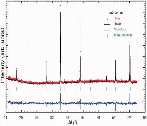
Figure 1. XRD patterns along with Riveted refinement of Mg2TiO4 ceramic target material sintered at 1350°C. The circles and solid line present the experimental and the Rietveld refined data, respectively. The dotted line at the bottom shows the difference between the experimental and the refined data. The vertical bars correspond to the allowed Bragg's peaks.

Table 1. Parameters obtained from the Rietveld analysis for MTO target materials sintered at 1350°C. χ 2, R Brag and Rf are reliability factors

Figure 2. XRD patterns of MTO films deposited on quartz substrate at different O2 SCCM for (a) as-deposited films and (b and c) annealed films.
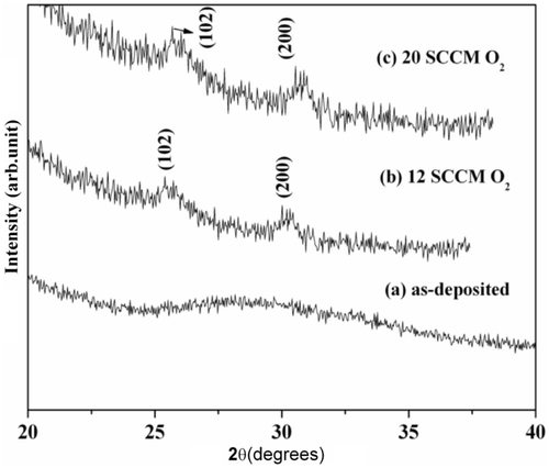
Figure 2. XRD patterns of MTO films deposited on quartz substrate at different O2 SCCM for (a) as-deposited films and (b and c) annealed films.

Figure 3. FESEM images of MTO thin films deposited on quartz at 12 SCCM O2 for as-deposited and (b) annealed films.
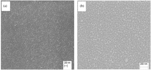
Figure 3. FESEM images of MTO thin films deposited on quartz at 12 SCCM O2 for as-deposited and (b) annealed films.

Figure 4. AFM surface morphology of MTO films deposited on quartz at 12 SCCM O2 for (a) as-deposited and (b) annealed films.
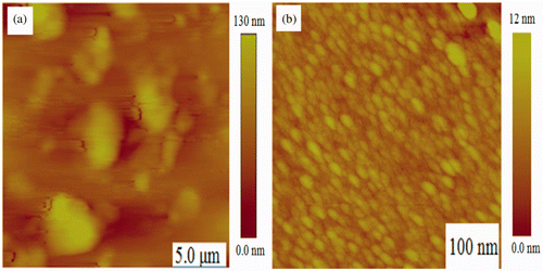
Figure 4. AFM surface morphology of MTO films deposited on quartz at 12 SCCM O2 for (a) as-deposited and (b) annealed films.

Figure 5. Optical transmittance spectra of MTO thin films deposited on quartz substrates for as-deposited at (a) 12 SCCM O2 (b) 28 SCCM O2 and annealed films deposited at (c) 12 SCCM O2 (d) 28 SCCM O2.
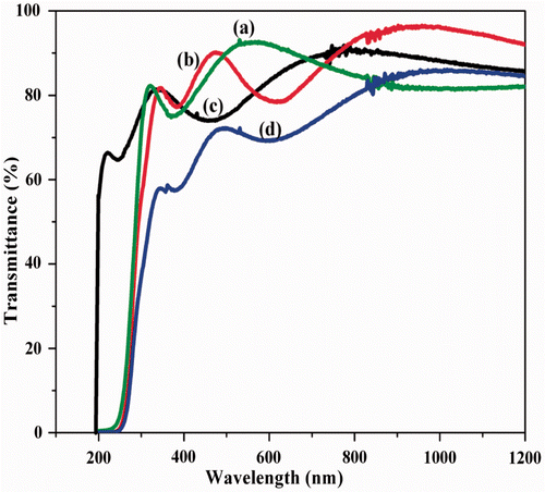
Figure 5. Optical transmittance spectra of MTO thin films deposited on quartz substrates for as-deposited at (a) 12 SCCM O2 (b) 28 SCCM O2 and annealed films deposited at (c) 12 SCCM O2 (d) 28 SCCM O2.

Figure 6. Variation of refractive index and packing density as a function of O2 SCCM for (a) as-deposited (inset) and (b) annealed films.
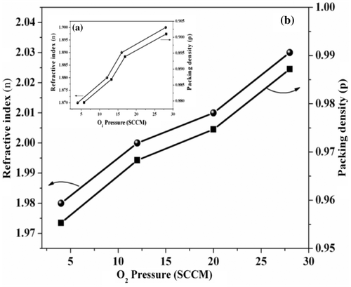
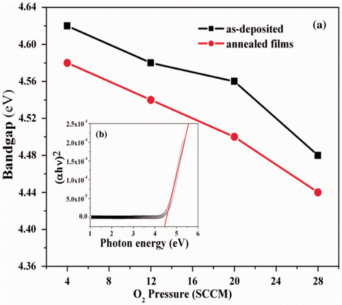
Figure 6. Variation of refractive index and packing density as a function of O2 SCCM for (a) as-deposited (inset) and (b) annealed films.
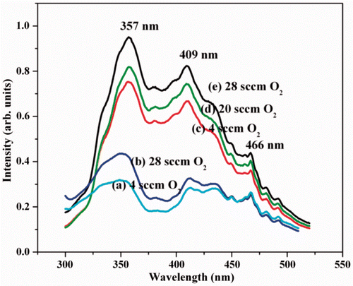
Figure 7. (a) Variation in bandgap as a function of O2SCCM for the as-deposited and annealed MTO films, (b) Inset shows the dependence of (αhν)2 against photon energy () for the annealed film deposited at 28 SCCM O2.

Figure 7. (a) Variation in bandgap as a function of O2SCCM for the as-deposited and annealed MTO films, (b) Inset shows the dependence of (αhν)2 against photon energy (hν) for the annealed film deposited at 28 SCCM O2.

Figure 8. PL spectra of MTO films deposited at different O2 SCCM for (a and b) as-deposited films and (c–e) annealed film.

Figure 8. PL spectra of MTO films deposited at different O2 SCCM for (a and b) as-deposited films and (c–e) annealed film.

Reprints and Corporate Permissions

Please note: Selecting permissions does not provide access to the full text of the article, please see our help page How do I view content?

To request a reprint or corporate permissions for this article, please click on the relevant link below:

Academic Permissions

Please note: Selecting permissions does not provide access to the full text of the article, please see our help page How do I view content?

Obtain permissions instantly via Rightslink by clicking on the button below:

If you are unable to obtain permissions via Rightslink, please complete and submit this Permissions form. For more information, please visit our Permissions help page.