Figures & data
Figure 1. Schematic diagram of the torsional fretting tester under a ball-on-flat contact.
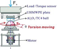
Figure 2. T–θ curves of TiO2/PMMA under various torsional angular amplitudes and cycles, Fn = 100 N. (a), (c), (e) and (g) TiO2/PMMA/Al2O3; (b), (d), (f) and (h) TiO2/PMMA/Ti6Al4V.
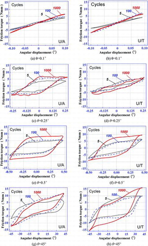
Figure 3. Friction torque under various angular displacements and different normal loads.
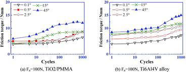
Figure 4. SEM morphologies of the alumina femoral head and Ti6Al4V alloy ball under lower angular displacements, Fn = 100 N, θ = 0.5°.
Figure 5. SEM micrographs of the worn scars under torsional fretting condition. Fn = 100 N, θ = 15°. (a), (b) and (c) TiO2/PMMA/Al2O3; (d), (e) and (f) TiO2/PMMA E/Ti6Al4V.
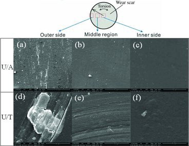
Figure 6. SEM micrographs of the ripple on worn scars, TiO2/PMMA/Al2O3. (a) Fn = 100 N, θ = 5°; (b) Fn = 100 N, θ = 15°; (c) Fn = 200 N, θ = 45°.
Figure 7. SEM micrographs of the scratch on worn scars of TiO2/PMMA/Ti6Al4V alloy ball. (a) Fn = 100 N, θ = 15°; (b) Fn = 200 N, θ = 15°; (c) Fn = 200 N, θ = 45°.
Figure 8. (Colour online) Optical micrographs of worn ball surface, θ = 45º, Fn = 100 N. (a) worn Al2O3 ball; (b) worn Ti6Al4V ball.
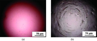
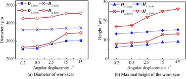
Figure 9. The diameter and maximal height of the worn scar under various angular displacement and different normal loads Fn = 200 N, (DA - diameter of the worn scar of U/A; DT - diameter of the worn scar of U/T; HA - maximal height of the worn scar of U/A; HT - maximal height of the worn scar of U/T; ΔD = DA − DT; ΔH = HA − HT).