Figures & data
Figure 1. The moulds fabrication for microfluidic colour-changing devices by using EtertecHT-115T dry film photoresist. (a) Peel off one of the translucent substrates from dry film photoresist. (b) Laminate the dry film photoresist (10 cm ×10 cm) on the cleaned mirror stainless steel substrate (10 cm ×10 cm ×2.5 cm) by using an office laminator at 110. (c) Overlap the three sheets (PMMA cover plate, prepared photomask sheet and mirror stainless steel substrate) as shown. (d) Fix around with clips to avoid light leaking. (e) Irradiate under 365 nm UV lamp at a distance of 15 cm. (f) Peel off the other translucent substrate from the dry film photoresist. (g) Immerse in 1% (mass concentration) Na2CO3 solution for developing. (h) Clean the developed structure with deionised water and dry it in nitrogen stream.
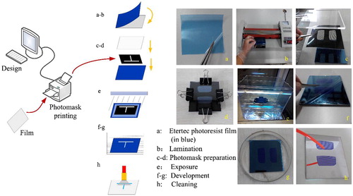
Figure 2. Fabrication process of the microfluidic colour-changing devices by using dry film moulds. (a) Fabrication of the PDMS film with microstructures. (b) Irreversible bonding of PDMS film with substrate (glass, resin or plastic).
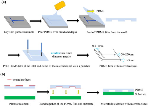
Figure 3. The effect of bubble on dry film mold. (a) Two formed bubbles between EtertecHT-115T dry film photoresist and mirror stainless steel substrate after lamination. (b) The irregular channel boundary caused by bubble.
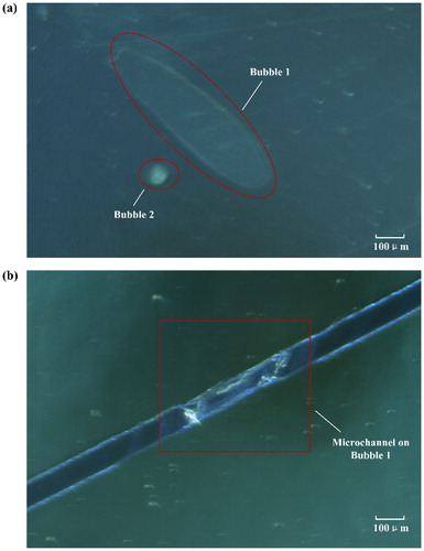
Figure 4. Microscope images of the microfluidic channels under different exposure times for different dry film photoresist thickness. (a) 50 μm thick, (b) 100 μm thick, (c) 150 μm thick.
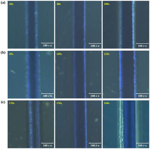
Figure 5. Experimental results of exposure times and developing times for 1–5 layers (50–250 μm thick) of EtertecHT-115T dry film photoresists. (a) The optimal exposure times, (b) The developing times by using different concentrations of developer solution.
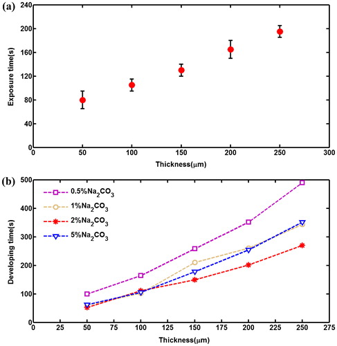
Table 1. Time-consuming comparison of using dry film photoresist and standard photolithography.
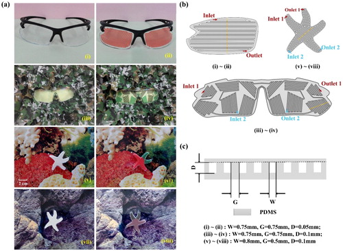
Figure 6. The applications of microfluidic colour-changing devices fabricated by dry film moulds. (a) The colour-changing effects of different microfluidic devices: (i) and (ii) colour-changing glasses, (iii) and (iv) camouflage glasses, (v)–(viii) colour-changing starfish. (b) Designs of the microstructures in . (c) Cross-sectional schematic of the regions indicated by the dotted yellow lines in .