Figures & data
Figure 1. Schematic representation of the SFCCVD reactor.
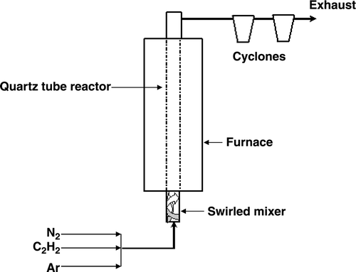
Figure 2. (a) TEM image of CSs produced by the SFCCVD technique at 900°C with C2H2 gas flow rate of 118 mL min−1. (b) Corresponding HRTEM image of the CSs. (c) HRTEM image of CSs synthesised in a horizontal furnace with the diffraction pattern of the shell of the CS (inset).
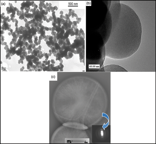
Figure 3. TGA profile of CSs in an oxidising (air) atmosphere.
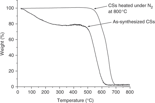
Figure 4. HRTEM image of CSs after heating at 800°C under nitrogen flow.
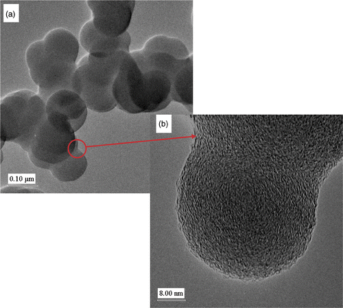
Figure 5. Rate of CS production at different temperatures and flow rate of acetylene.
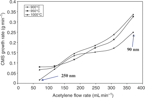
Table 1. Diameters of CSs produced at different temperatures and C2H2 gas flow rates.
Figure 6. Effects of carrier gas on rate of CS production at constant flow rate of acetylene and temperature.
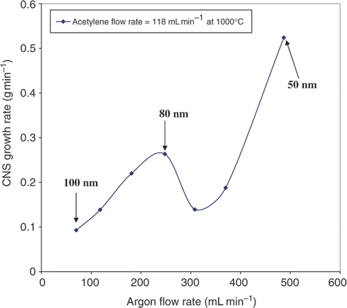
Figure 7. TEM images of CSs synthesised with Ar as carrier gas at (a) 487 mL min−1, (b) 248 mL min−1 and (c) 70 mL min−1. Histograms for the corresponding size distributions of the CSs are shown on the right side of the TEM images.
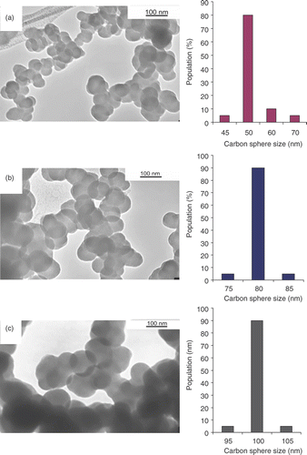
Figure 8. PXRD patterns of CSs synthesised using the SFCCVD technique.
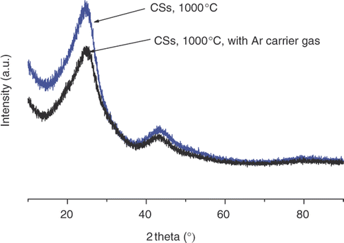
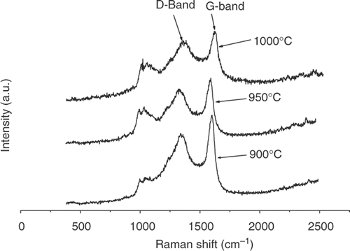
Figure 9. Raman spectra of CSs.