11,062
Views
174
CrossRef citations to date
0
Altmetric
REVIEW ARTICLE

Thermo-hydro and thermo-hydro-mechanical wood processing: An opportunity for future environmentally friendly wood products

, &
Pages 64-88 | Received 30 May 2012, Accepted 15 Nov 2012, Published online: 18 Dec 2012

Figures & data

Table I. Sugar analysis of aspen before and after heat treatment with saturated steam at 220°C in a closed system for 8 minutes (Rowell et al. Citation2009).

Figure 1.  Bending of bows from a facsimile of a wall painting in the tomb of the nomarch Amenemhat at Beni Hasan, ca. 1971–1928 B.C. A nomarch was the semi-feudal ruler of an Ancient Egyptian province (Newberry Citation1893)
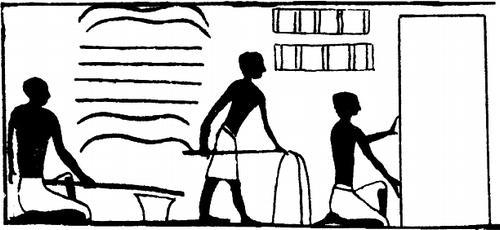
Figure 1.  Bending of bows from a facsimile of a wall painting in the tomb of the nomarch Amenemhat at Beni Hasan, ca. 1971–1928 B.C. A nomarch was the semi-feudal ruler of an Ancient Egyptian province (Newberry Citation1893)

Figure 2.  Stress-strain (σϵ) diagrams for air-dried non-plasticized beech and plasticized beech. Note that the strain axis has different scales to the right and to the left of the origin (after Prodehl Citation1931a,Citationb). MC, moisture content
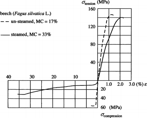
Figure 2.  Stress-strain (σ–ϵ) diagrams for air-dried non-plasticized beech and plasticized beech. Note that the strain axis has different scales to the right and to the left of the origin (after Prodehl Citation1931a,Citationb). MC, moisture content

Figure 3.  Various modes of deformation of the cell walls of wood under compression in the longitudinal direction; (a) plastic deformation of the cell wall (formation of slip planes), (b) lateral buckling of the cell walls, (c) localised shearing band, (d) diffuse buckling of the cell walls
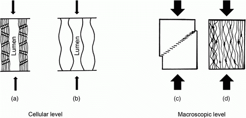
Figure 3.  Various modes of deformation of the cell walls of wood under compression in the longitudinal direction; (a) plastic deformation of the cell wall (formation of slip planes), (b) lateral buckling of the cell walls, (c) localised shearing band, (d) diffuse buckling of the cell walls

Figure 4.  Diagrammatic representation of the mechanisms of local deformation of wood cells under a longitudinal compression force; (a) wood before the application of the force, (b) collapse of fibre by rupture, (c) collapse by the buckling of cell walls
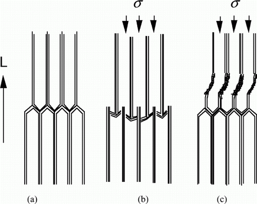
Figure 4.  Diagrammatic representation of the mechanisms of local deformation of wood cells under a longitudinal compression force; (a) wood before the application of the force, (b) collapse of fibre by rupture, (c) collapse by the buckling of cell walls

Figure 5.  Micrograph of uniformly densified spruce latewood cells after compression at 140°C under saturated moisture conditions (Navi and Heger Citation2005). Micrograph of the boundary between the compressed surface and uncompressed regions of wood (Inoue et al. Citation1990)
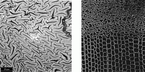
Figure 5.  Micrograph of uniformly densified spruce latewood cells after compression at 140°C under saturated moisture conditions (Navi and Heger Citation2005). Micrograph of the boundary between the compressed surface and uncompressed regions of wood (Inoue et al. Citation1990)

Figure 6.  Schematic illustration of wood densification in the transverse direction at the cell level, recovery and different methods of fixation of the compression set: (a) initial undeformed state, (b) softening of the wood by steam, (c) densification, (d) cooling, (e) total set recovery, (f) mechanical fixation, (g) chemical fixation or fixation by a THM treatment
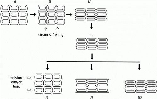
Figure 6.  Schematic illustration of wood densification in the transverse direction at the cell level, recovery and different methods of fixation of the compression set: (a) initial undeformed state, (b) softening of the wood by steam, (c) densification, (d) cooling, (e) total set recovery, (f) mechanical fixation, (g) chemical fixation or fixation by a THM treatment

Figure 7.  Movements, velocities and forces in four different types of frictional welding; (a) linear friction, (b) orbital friction, (c) circular friction and (d) rotary friction welding (Stamm Citation2005)
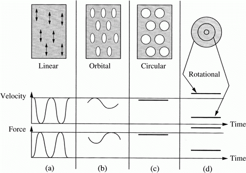
Figure 7.  Movements, velocities and forces in four different types of frictional welding; (a) linear friction, (b) orbital friction, (c) circular friction and (d) rotary friction welding (Stamm Citation2005)

Figure 8.  Cross-sectional profile of a dowel ligno-bonded by rotary friction welding (Ganne-Chédeville et al. Citation2005)
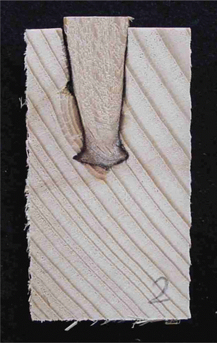
Figure 8.  Cross-sectional profile of a dowel ligno-bonded by rotary friction welding (Ganne-Chédeville et al. Citation2005)

Figure 9.  Micrograph of a zone of joined and adjacent areas between two pieces of spruce welded by circular friction (Stamm et al. Citation2005a)
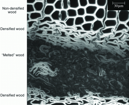
Figure 9.  Micrograph of a zone of joined and adjacent areas between two pieces of spruce welded by circular friction (Stamm et al. Citation2005a)

Figure 10.  A wooden multi-layer element made of alternate layers of spruce and beech bonded by circular friction welding (Stamm Citation2005)
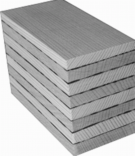
Figure 10.  A wooden multi-layer element made of alternate layers of spruce and beech bonded by circular friction welding (Stamm Citation2005)

Figure 11.  Compwood machine for pre-compression of wood in the longitudinal direction to make it bendable in a cold state (view from above). The operations are: (a) loading, (b) autoclave for plasticizing the wood, (c) automatic input, (d) machine for longitudinal compression, and (e) output of densified wood
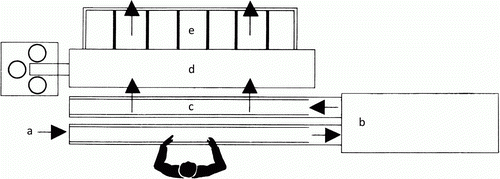
Figure 11.  Compwood machine for pre-compression of wood in the longitudinal direction to make it bendable in a cold state (view from above). The operations are: (a) loading, (b) autoclave for plasticizing the wood, (c) automatic input, (d) machine for longitudinal compression, and (e) output of densified wood

Figure 12.  Thermo-hydro-mechanical apparatus and the internal moulding block (left) and transformation of a circular trunk to a square-section block by two-dimensional densification (right) (Ito et al. Citation1998a)
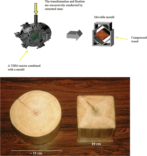
Figure 12.  Thermo-hydro-mechanical apparatus and the internal moulding block (left) and transformation of a circular trunk to a square-section block by two-dimensional densification (right) (Ito et al. Citation1998a)

Figure 13.  Wood tube of densified spruce (left) and filament winding of moulded tubes (right)

Figure 13.  Wood tube of densified spruce (left) and filament winding of moulded tubes (right)

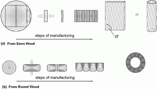
Figure 14.  Manufacture of wooden tubes from (a) sawn wood and (b) a log

Figure 14.  Manufacture of wooden tubes from (a) sawn wood and (b) a log

Figure 15.  Moulding of a densified wood panel to a tube of diameter 450 mm; (a) charging, (b) closing, (c) forming. The thickness of the tube wall is 100 mm
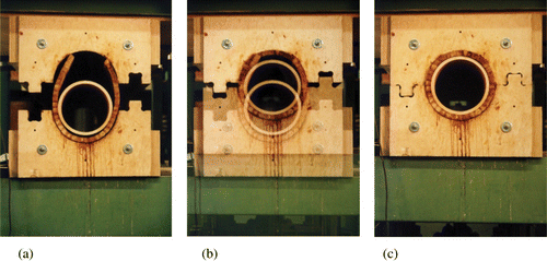
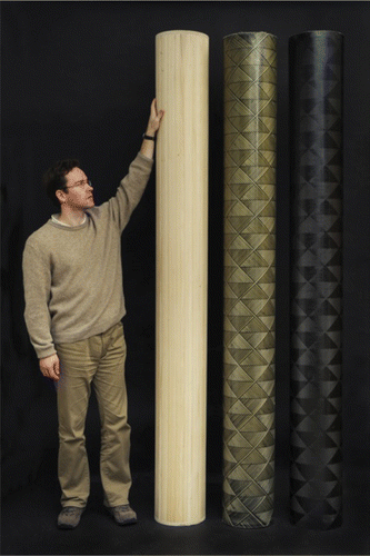
Figure 15.  Moulding of a densified wood panel to a tube of diameter 450 mm; (a) charging, (b) closing, (c) forming. The thickness of the tube wall is 100 mm