Figures & data
Figure 1. Time series chart of the prevalence of obesity (BMI > 30) among adults, ages 18+, 1975–2020, in Slovakia. Source: Riley (Citation2022).
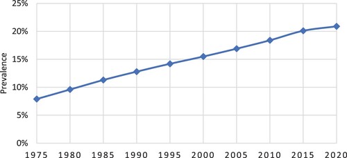
Figure 2. Minimal space required to change the position of the body in the bed comfortably from a centred position: 1TD – to turn in one side, 2TD – to turn in two sides (Wiggermann et al. Citation2017).
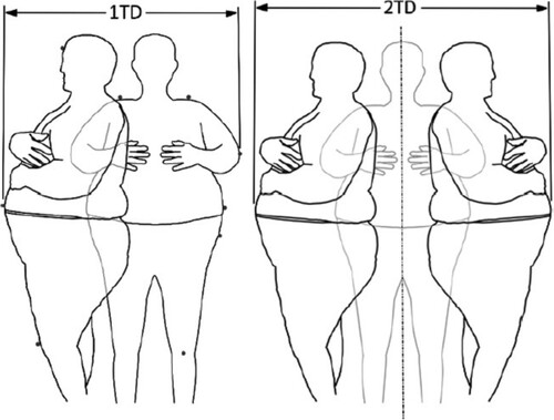
Table 1. Mechanical properties of lamellae (Réh et al. Citation2019).
Figure 3. Shape and dimensions of lamella in bariatric beds.
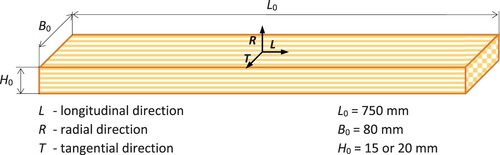
Figure 4. Scheme of the three-point bending test of the lamella (CEN Citation1993).
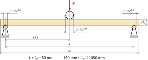
Table 2. Parameters to design the lamella thickness.
Table 3. Descriptive statistics of 225 bariatric respondents.
Figure 5. Example of a bed construction.
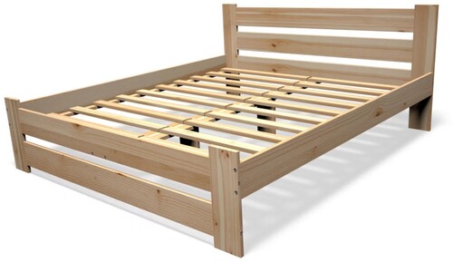
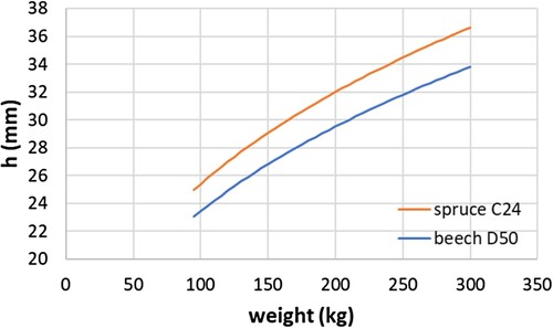
Figure 6. Force and bending diagrams: (a) spruce wood (h = 20 mm), (b) beech wood (h = 15 mm). The dashed line shows the result of the FEM simulation.
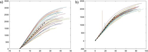
Table 4. Bending characteristics of bed lamellae.
Figure 7. Correlation between strength, modulus of elasticity, and density.
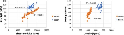
Figure 8. Finite element calculation model for three-point board bending.
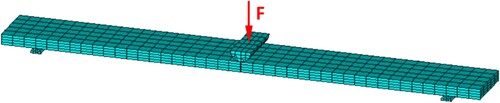
Figure 9. Deflection in three-point bending of beech lamella (board) (board thickness h = 15.3 mm, loading force F = 2500 N).
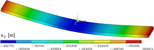
Figure 10. Tensile stress in the fibre direction in the three-point bending of beech lamella (board) (board thickness h = 15.3 mm, loading force F = 2500 N).
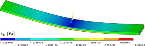
Figure 11. Maximum lamella stress after meeting the allowable deflection limit criteria.
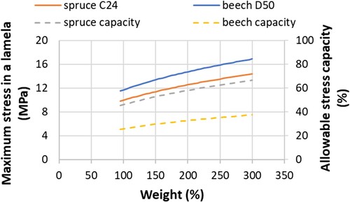
Figure 12. The minimum thickness of bed lamellae for bariatric respondents.