Figures & data
Figure 1. Cross-section view of a branch of Norway spruce with compression wood and opposite wood taken by μCT scanning. The arrow showing the stem direction indicates the growth direction of the main stem of the tree.
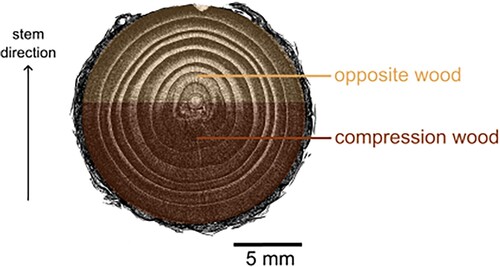
Figure 2. Schematic illustration of beam design concepts in engineering and in nature, demonstrated by a softwood beam.
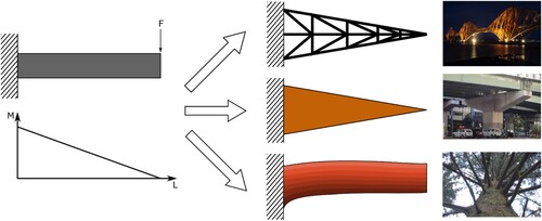
Figure 3. Comparison of a branch and the Euler–Bernoulli beam model.
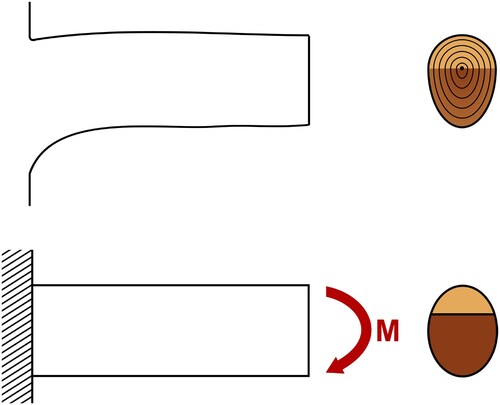
Table 1. Mechanical properties of compression and opposite wood in Norway spruce.
Figure 4. Maximum moment depending on area proportion of compression wood in a branch cross section as also schematically indicated above the graph; light colour corresponds to OW and dark colour to CW. The shaded area shows relative amounts of CW found in softwood branches (Low Citation1964, Harris Citation1977, Spicer and Gartner Citation1998, Li et al. Citation2014).
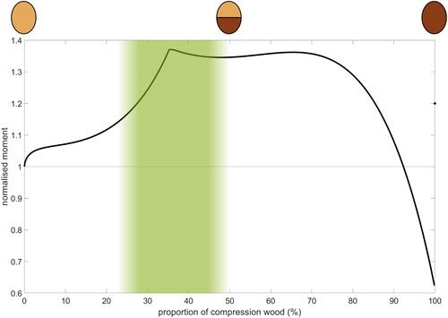
Figure 5. Stress and strain profiles in beam bending of a branch with 25% CW.
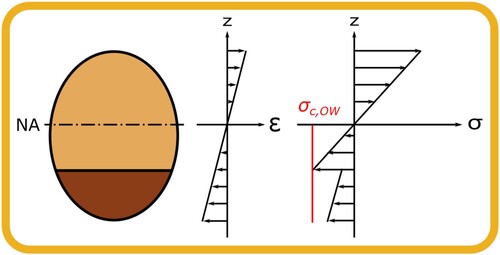
Figure 6. Stress and strain profiles in beam bending of a branch with 50% CW.
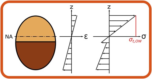
Figure 7. Moment corresponding to the governing stress states. Compressive governing stress state in OW (yellow), tensile governing stress state in OW (orange), compressive governing stress state in CW (blue) occur depending on the proportion of compression wood in the branch. The shaded area shows relative amount of CW found in softwood branches.
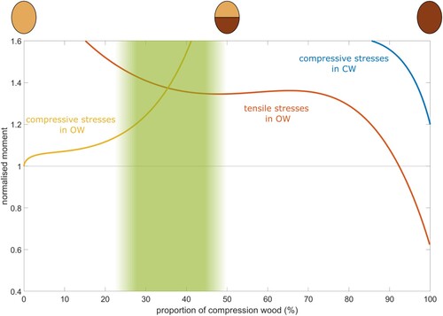
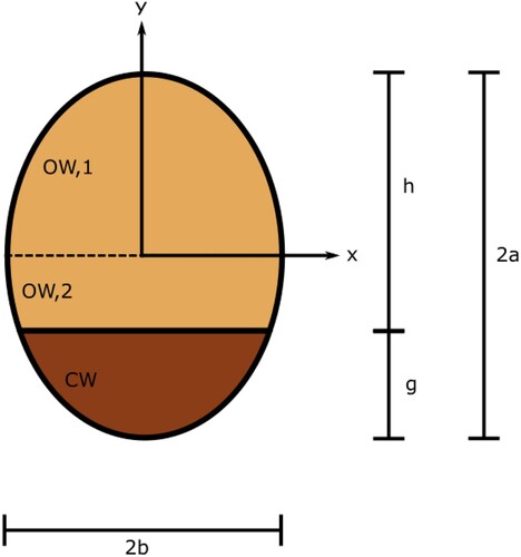
Figure A1. Idealized elliptical cross-section containing both OW and CW.