Figures & data
Figure 1. Overview of the Inductive Tongue Computer Interface. The Inductive Tongue Interface transmits the 18 sensor signals wirelessly out of the mouth to the central unit, which processes the signals and transmits the processed information to the PC unit, which emulates a mouse/keyboard function. The board used for the PC unit includes a microcontroller and radio chip.[Citation24]
![Figure 1. Overview of the Inductive Tongue Computer Interface. The Inductive Tongue Interface transmits the 18 sensor signals wirelessly out of the mouth to the central unit, which processes the signals and transmits the processed information to the PC unit, which emulates a mouse/keyboard function. The board used for the PC unit includes a microcontroller and radio chip.[Citation24]](/cms/asset/16dd4046-886b-4b75-a447-8e07db96a274/iidt_a_1217084_f0001_c.jpg)
Figure 2. Overview of the ITI parts. Top: The Two 10-layer PCB constituting the key pad (left) and the mouse pad (right), the battery and the PCB for the electronics. The scale is in centimeters. Middle: Top middle: The assembled ITI parts, showing the charger coil and the sensor PCB. Bottom middle: The battery and one of the flex prints used to connect the parts. Bottom: The fully embedded ITI dental appliance.
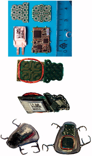
Figure 3. Overview of the main parts of the ITI signal processing and detection system. (a) The steps in the signal processing system. (b) The ideal principle of measurement: a band-pass filter was created by connecting a capacitor to each sensor coil. (c) During activation the impedance of the LC band-pass filter changed, and the activation was detected at the frequency, fmeas, indicated by the vertical punctured line. (d) The real frequency characteristics of the detection LC band pass filter with and without sensor activation.
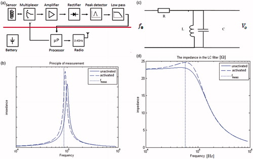
Figure 4. Left: The stainless steel frame forming the base of the encapsulation of the electronic parts. Right: The activation unit glued to the tongue.
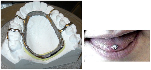
Figure 5. The filter structure used for removal of the baseline from the sensor signals.
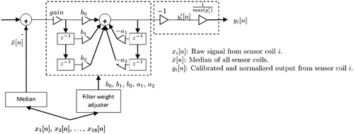
Figure 6. The method for adjustment of the filter weights for the filter () for removal of the sensor offset and drift.
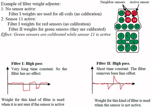
Figure 7. The sensors and the related typing functionality in mouse mode (left sensor layout) and keyboard mode for full alphabet text input (right sensor layout). Switching between keyboard and mouse modes was performed by activating sensor number 10 for 10 sec. Adapted from Lontis et al. [Citation29]
![Figure 7. The sensors and the related typing functionality in mouse mode (left sensor layout) and keyboard mode for full alphabet text input (right sensor layout). Switching between keyboard and mouse modes was performed by activating sensor number 10 for 10 sec. Adapted from Lontis et al. [Citation29]](/cms/asset/9d3b4c6e-5e64-43b0-973e-d79a5bac8ac6/iidt_a_1217084_f0007_c.jpg)
Figure 8. Typing procedure: when a sensor on the keypad area was activated, in this case sensor 2, the first character related to that sensor was displayed as a visual feedback for the user. If the sensor was still activated after a time period, called dwell time 1 (D1), it could be typed during the following time period, dwell time two (D2), during which deactivation of the sensor would result in typing of an “a”. If the sensor was activated beyond D2, the next character related to sensor 2 which was “b” was displayed, and deactivation of the sensor would then cause a “b” to be typed. If the sensor was still not deactivated, the next character related to the sensor would appear, and this procedure would continue in a circular manner until the sensor was deactivated. If the sensor was deactivated during D1, the “a” would be deleted and no character would be typed. This gave the user a time period, D1, to slide on the keypad area, with visual feedback, without typing undesired characters.
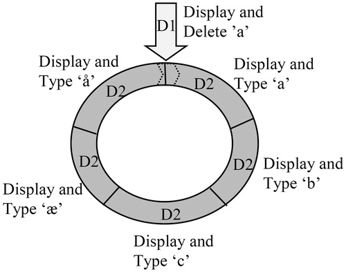
Figure 9. The Matlab© based visual feedback used in the experiments. The given character string to be typed is shown with the currently desired character in capital. In the text field above, the characters typed by the subject are displayed. Correctly typed characters are shown in capital. A figure below the text field shows the position of the characters on the keypad area of the ITCI. As default, all sensors were marked with a green circle. When the activation unit was placed at a sensor/character for less than the time D1, the circle around the character turned yellow, and the character was temporarily typed at the cursor in the text field. When D1 was exceeded, the colour turned from yellow to red and deactivation of the sensor resulted in sustained typing of the character in the text field after which the cursor moved one step forward to provide feedback for the next character to be activated by the subject. If no deactivation occurred within the time D2, the next character related to the activated sensor was displayed.
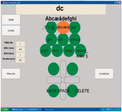
Table 1. Tasks for typing with the Matlab interface.
Figure 10. The number of correctly typed characters in trials of 30 sec duration. Trials for the healthy subjects S3 and S4 using the keypad area. The results are for trial 1 to 17 in .
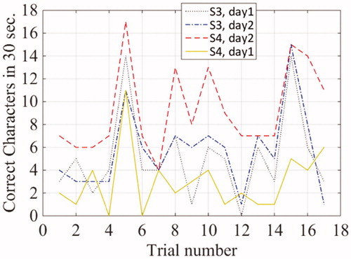
Figure 11. The number of correctly typed characters in trials of 30 sec. for the individuals with tetraplegia, S1 and S2 using the keypad area. The shown results are for trial 1 to 16 in .
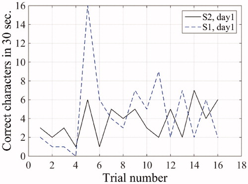
Table 2. Mean and average typing times for all subjects in trials of 30 sec.
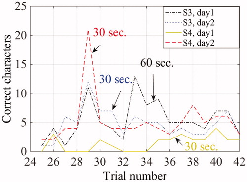
Figure 12. The number of correctly typed characters for S3 and S4 using the on-screen keyboard with the ITCI mouse pad area. The trial number refers to the numbers in + 24, e.g., the characters typed in Trial 29 are “aaa”. Trial durations of the trials are shown in the figure.