
Figures & data
Figure 1. The robotic anatomical model propulsion system wheelchair testbed.
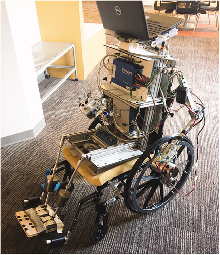
Table 1. Wheel properties.
Figure 2. Cross-sectional tire profiles.
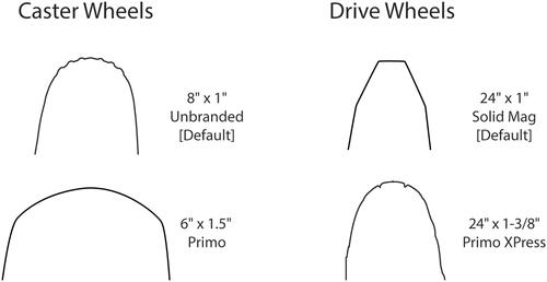
Table 2. Configurations used to assess performance.
Figure 3. Torque profile for the Straight manoeuvre on tile.
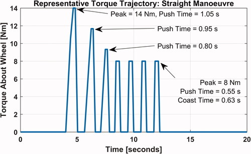
Figure 4. Torque profile for the Slalom manoeuvre on tile.
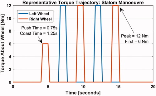
Table 3. Coast-down deceleration values over tile and carpet.
Table 4. Cost and distance during straight manoeuvre on tile.
Figure 5. Superiority test results for the Straight manoeuvre over tile.
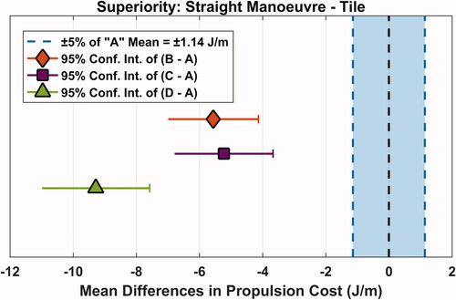
Table 5. Cost distance, and yaw displacement during the Slalom manoeuvre on tile.
Figure 6. Superiority test results for the Slalom manoeuvre over tile.
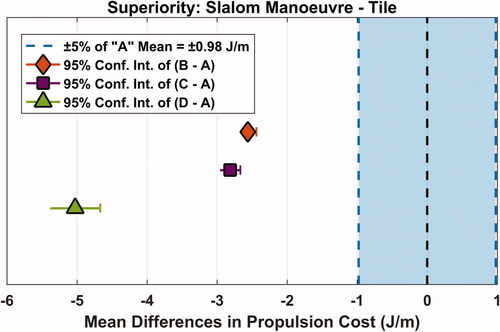
Table 6. Cost and distance during the Straight manoeuvre on carpet.
Figure 7. Superiority test results for the Straight manoeuvre over carpet.
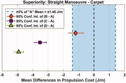
Table 7. Cost, distance, and yaw displacement during the Slalom manoeuvre on carpet.
Figure 8. Superiority test results for the Slalom manoeuvre over carpet.
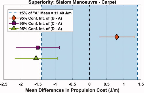
Table 8. Component cost comparisons from online retailers.