935
Views
5
CrossRef citations to date
0
Altmetric
Original Articles

A didactical note on the advantage of using two parameters in Hopf bifurcation studies

&
Pages 21-30 | Received 16 May 2012, Accepted 14 Dec 2012, Published online: 17 Jan 2013

Figures & data

Figure 1. Bifurcation diagram in the (α12)-plane showing a transcritical bifurcation curve (red) and Hopf bifurcation curves (blue) for kπ<ω<(k+1) π with k=0, 1, 2. The numbers of eigenvalues in the right half of the complex plane are indicated in the boxes. Each number (box) corresponds to a region bounded by the bifurcation curves.
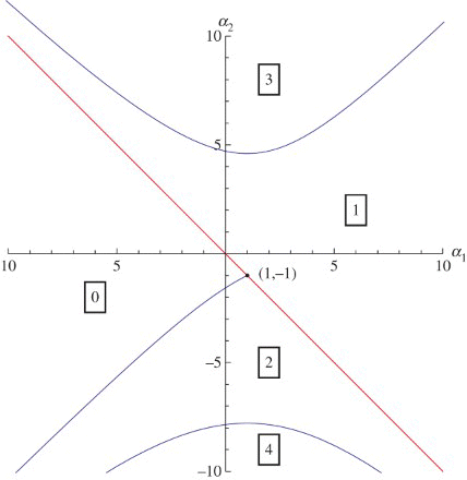
Figure 1. Bifurcation diagram in the (α1,α2)-plane showing a transcritical bifurcation curve (red) and Hopf bifurcation curves (blue) for kπ<ω<(k+1) π with k=0, 1, 2. The numbers of eigenvalues in the right half of the complex plane are indicated in the boxes. Each number (box) corresponds to a region bounded by the bifurcation curves.

Figure 2. Critical values of the parameters δ, 2 e−γ, and β0 and the Hopf period T for n=3. The transition from a stable steady state to an unstable steady state happens when we pass from below the curve to above the curve or when β0 increases from below the critical value to above . For ω=0 we have .
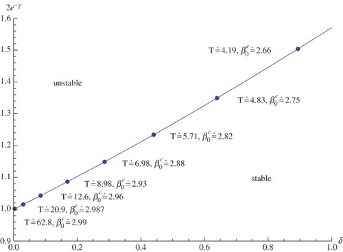
Figure 2. Critical values of the parameters δ, 2 e−γ, and β0 and the Hopf period T for n=3. The transition from a stable steady state to an unstable steady state happens when we pass from below the curve to above the curve or when β0 increases from below the critical value to above . For ω=0 we have .
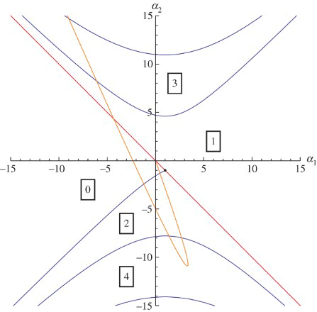
Figure 3. repeated with a superimposed curve parametrized by δ in the (α12)-plane corresponding to δ∈(0, 3), β0=1.77, γ=0.2 and n=12.

Figure 3. Figure 1 repeated with a superimposed curve parametrized by δ in the (α1,α2)-plane corresponding to δ∈(0, 3), β0=1.77, γ=0.2 and n=12.