Figures & data
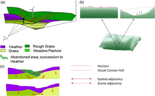
Figure 1. A computer-generated scene (a) of the corresponding map (b) and viewshed (c) showing two land cover classes, for example, grassland (light green) and heather (dark green), in the viewshed (c) occluded area is blank. Arrows show field of view.
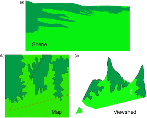
Figure 2. (a) Maintaining a current horizon for HSR (inset shows horizon edge within TIN) and (b) the resulting information in orthographic and perspective views.
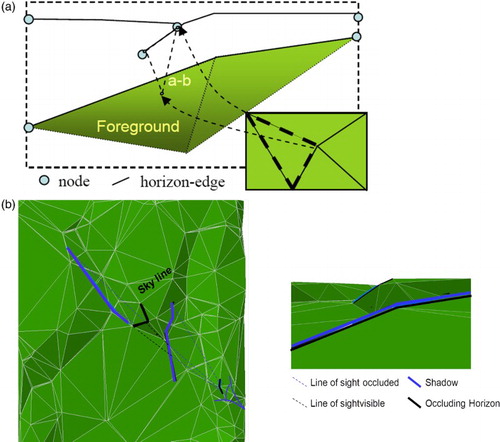
Figure 3. (a) Lines of sight to topological events in the scene and (b) the ‘visual hull’ they form spatially.
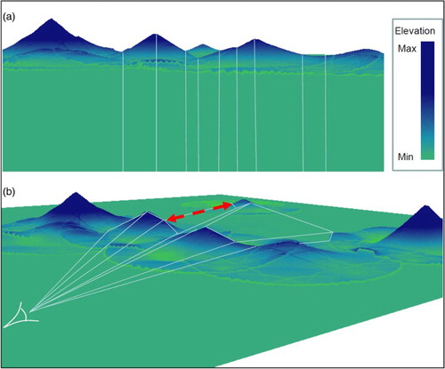
Figure 4. (a) Quad-Edge Delaunay TIN and the Voronoi dual, and (b) embedding line of sight pointers. A ‘Quad-Edge’ (cross shape) is a set of four pairs of ‘Quads’ (squares). A Quad is a set of pointers. One pointer references the next Quad in the Quad-Edge, the other either points to one node at the end of the TIN edge (Green), or to one of the triangle faces either side (Red) – colours are greyed out for visually occluded quads. By following the pointers, it is possible to navigate the TIN.
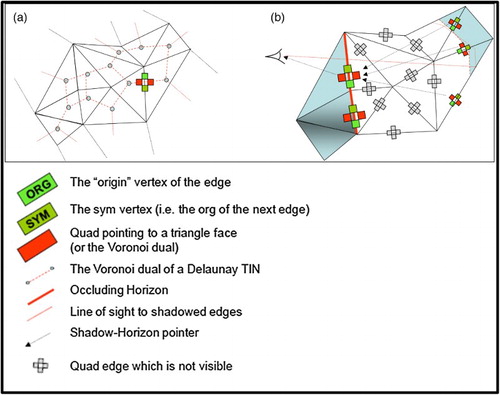
Figure 5. (a) Scanning a mesh in three spirals, after Gold et al. (Citation1996), (b) horizon determination, (c) visual intersection points, and (d) the horizon graph (note that shadow–horizon links need only be recorded when the shadowed edge is itself a horizon.
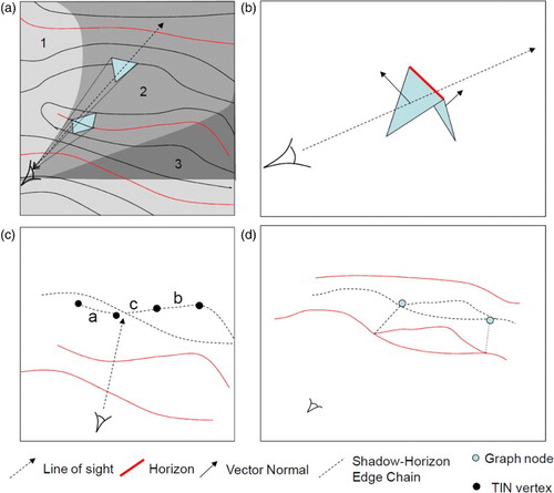
Figure 6. (a) Rendering of test data set in ArcGIS and (b) output from VM-LITE showing the viewshed (purple), horizons (yellow), and shadow–horizon links (green).
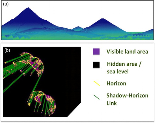
Figure 7. Embedding shadow–horizon links into a Quad-Edge TIN.
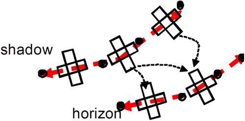
Figure 8. Landscape change as measured by patch count in viewshed (a, c) and scene (b, d).
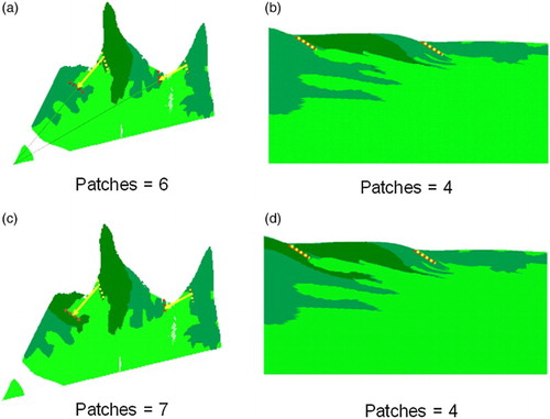
Figure 9. (a) Establishing scene properties via shadow–horizon pointers, (b) scene framing effects, and (c) scene patch complexity.