Figures & data
Figure 1. Virtual scene of the Virtual Reality Hall. The white part on the left is a huge spherical screen wall. The pillars are in the top right of the figure and the outer wall is behind the pillars. The structure error of this model is around 10 cm.
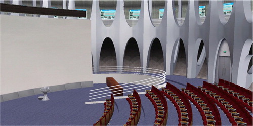
Figure 2. Camera positions in the Virtual Reality Hall. The green points are the surveillance cameras. Each camera is installed at the junction of two pillars and captures videos from an oblique view.
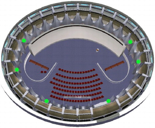
Figure 3. Screenshots of video data. (a) Camera 140; (b) Camera 143; (c) Camera 142; (d) Camera 141. The resolution of each video is 1280 × 720, and there are some overlapping areas between two adjacent videos, such as (a) and (b).
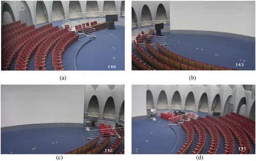
Figure 4. Flowchart for creating an AVE in the Digital Earth system.
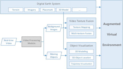
Figure 5. Result before and after applying the depth test algorithm. P: the projector. A: the walls and pillars nearest to the projector. B: the surfaces behind the pillars.
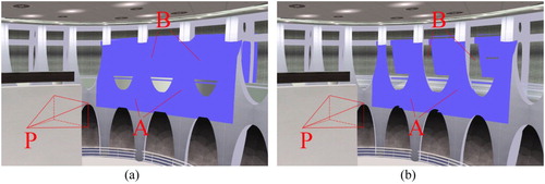
Figure 6. Difference in texture coordinate systems. Two textures A and B have their own separate texture coordinate systems, and
.
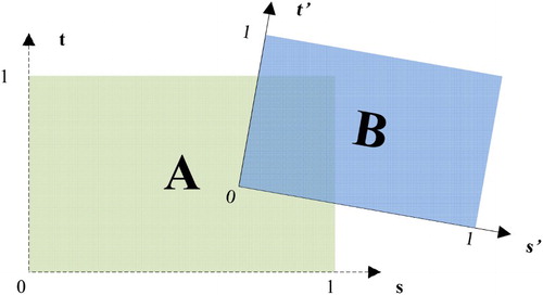
Figure 7. Ordinal relations of video textures.
Table 1. Texture coordinates of overlapping areas in .
Figure 8. Diagram of the diagonally weighted algorithm.
Figure 9. Weight isolines of regular relations between video textures.
Figure 10. Weight isolines of irregular relations between video textures.
Figure 11. Stretched moving object. (a) Front view from the virtual projector and (b) oblique view.
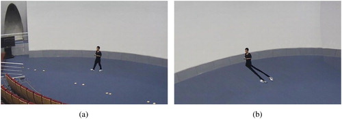
Figure 12. Examples of an object silhouette with texture. P: the bottom middle point of the silhouette.
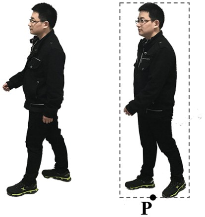
Figure 13. Flowchart of object location and trajectory visualization in a 3D scene.
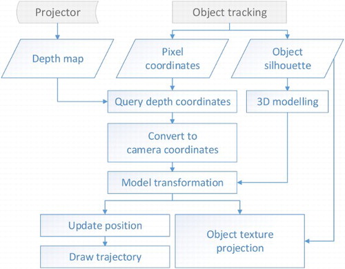
Figure 14. Multiple video mapping with the original projective texture mapping algorithm. A: the glass turns opaque; B: obvious video texture gap; C: incorrectly projected video texture.
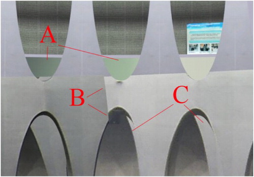
Figure 15. Example of the depth map. A: pillars; B: transparent glass; C: wall of the hall.
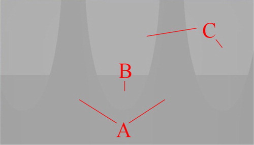
Figure 16. Result of the depth test algorithm and diagonally weighted algorithm.
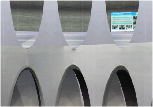
Figure 17. Result of fusing three video textures before being processed by the proposed algorithms. A and B: obvious gaps in video textures.
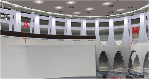
Figure 18. Result of fusing three video textures after being processed by the proposed algorithms.
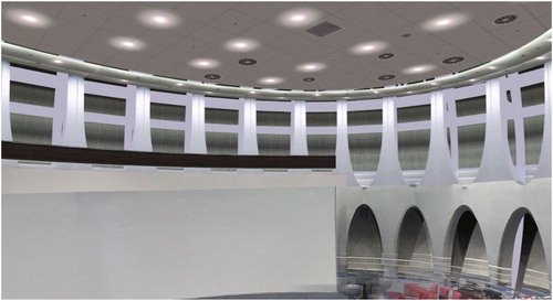
Figure 19. 3D visualization of the moving object. (a) Oblique view and (b) top view. A: 3D model in the virtual scene; B: fused video textures; C: rectangular model of the moving object.
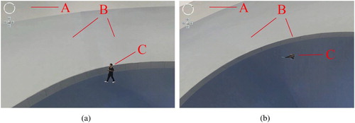
Figure 20. Trajectory of the moving object. The trajectory was linked by the sequential geographic coordinates of the moving object model.
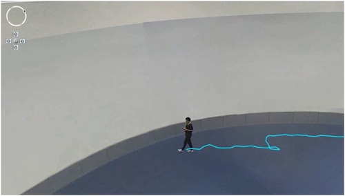
Table 2. Frame rates of the original projective texture mapping (fps).
Table 3. Frame rates of proposed multiple video texture fusion algorithm (fps).
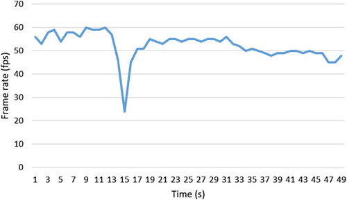
Figure 21. Frame rates of video fusion and object visualization in the DESP. The stage of only viewing the 3D model: 1–13 s. The multiple video textures fusion stage: 17– 33 s. The moving object visualization stage: 34– 39 s. The trajectory visualization stage: 40–49 s.