Figures & data
Figure 1. Picture of a core tank loaded with MOX rods and structures for the control blade core [Citation4]. Note: the number of MOX rods in the driver region is not the same as that of the critical core.
![Figure 1. Picture of a core tank loaded with MOX rods and structures for the control blade core [Citation4]. Note: the number of MOX rods in the driver region is not the same as that of the critical core.](/cms/asset/cc84f81d-c336-4931-aa8a-3b4462a20044/tnst_a_636553_o_f0001g.jpg)
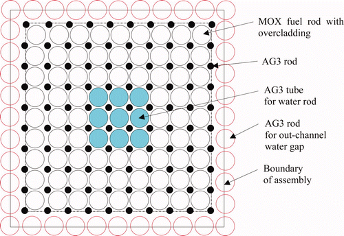
Figure 2. Schematic diagram of core radial configurations of critical cores [Citation3,Citation4]. (a) 9 × 9 reference core (0% void), (b) Control blade core (40% void), (c) UO2 rod core (40% void), (d) Gd2O3-UO2 rod core (40% void), (e) 10 × 10 assembly core (40% void), (f) Time-elapsed reference core (0% void). Note: “Pu(t) 3.0wt%” means a total-Pu content (include 241Am) of MOX pellets is 3.0 wt%, “AG3” is Aluminum alloy.
![Figure 2. Schematic diagram of core radial configurations of critical cores [Citation3,Citation4]. (a) 9 × 9 reference core (0% void), (b) Control blade core (40% void), (c) UO2 rod core (40% void), (d) Gd2O3-UO2 rod core (40% void), (e) 10 × 10 assembly core (40% void), (f) Time-elapsed reference core (0% void). Note: “Pu(t) 3.0wt%” means a total-Pu content (include 241Am) of MOX pellets is 3.0 wt%, “AG3” is Aluminum alloy.](/cms/asset/0680a382-acfd-4c4e-98e5-5c666e5cc9d7/tnst_a_636553_o_f0002g.jpg)
Figure 3. Schematic drawing of cross-section of cruciform control blade with B4C absorber rods [Citation7].
![Figure 3. Schematic drawing of cross-section of cruciform control blade with B4C absorber rods [Citation7].](/cms/asset/fd7e3031-f8dd-4a6c-9a92-14b91f53383c/tnst_a_636553_o_f0003g.gif)
Table 3. Fission rate distribution measurements and measured buckling values.
Figure 5. Multi-cell model for out-channel gap inserted with a cruciform control blade. Note: Ex. MOX 5.0wt%: homogenized cell of MOX rod of 5.0 (total Pu) wt%, moderator and structures.

Figure 6. Critical k eff's calculated with JENDL-3.3 for the FUBILA cores. Note: Critical k eff's of bold–italic faced cores show the present results and others those in Ref. [Citation9].
![Figure 6. Critical k eff's calculated with JENDL-3.3 for the FUBILA cores. Note: Critical k eff's of bold–italic faced cores show the present results and others those in Ref. [Citation9].](/cms/asset/b6cc126b-1c2e-4054-9785-8fd5172c1cc5/tnst_a_636553_o_f0006g.jpg)
Figure 7. Critical k eff's calculated by MVP. Note: Critical k eff's of bold–italic faced cores show the present results and others those in Ref. [Citation9].
![Figure 7. Critical k eff's calculated by MVP. Note: Critical k eff's of bold–italic faced cores show the present results and others those in Ref. [Citation9].](/cms/asset/6befc032-64f3-4332-b93e-ad996ae248c9/tnst_a_636553_o_f0007g.jpg)
Table 4. Critical k eff of the FUBILA cores.
Figure 8. Deviation of calculated radial fission rates of CITATION-2D calculation from measurements for the test region of the control blade core. Note: Deviation (%): (calculated fission rate −measured fission rate)/(measured fission rate) × 100.
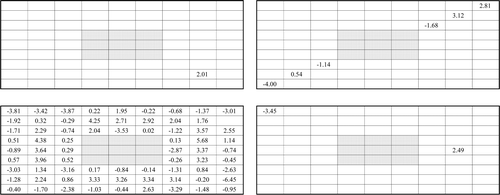
Figure 9. Deviation of calculated radial fission rates of TWODANT calculation from measurements for the test region of the control blade core. Note: Deviation (%): (calculated fission rate −measured fission rate)/(measured fission rate) × 100
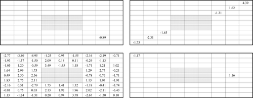
Table 5. Root-mean-square (RMS), maximum (Max) and minimum (Mini) values of (calculated–measured)/measured in % for radial fission rates in the test region.
Figure 10. Comparison between calculated fission rates of CITATION-2D and measurements in the diagonal direction of the test region of the control blade core. Note: The average values of fission rates are normalized to 1.0.
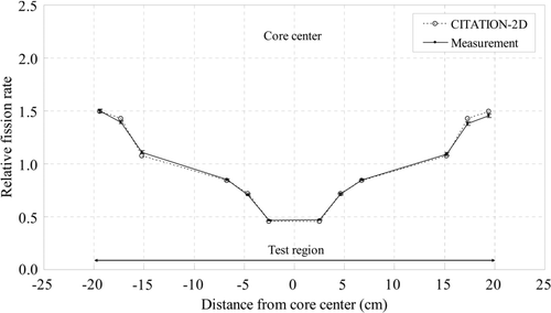
Figure 11. Deviation of calculated radial fission rates of CITATION-2D calculation from measurements for the test region of the Gd2O3-UO2 core [Citation12]. Note: Deviation (%): (calculated fission rate −measured fission rate)/(measured fission rate) × 100. Notation: Brown: UO2 rod, dark blue: Gd2O3-UO2 rod, light blue, white and yellow: MOX rods.
![Figure 11. Deviation of calculated radial fission rates of CITATION-2D calculation from measurements for the test region of the Gd2O3-UO2 core [Citation12]. Note: Deviation (%): (calculated fission rate −measured fission rate)/(measured fission rate) × 100. Notation: Brown: UO2 rod, dark blue: Gd2O3-UO2 rod, light blue, white and yellow: MOX rods.](/cms/asset/d327ec40-60cb-4c76-9918-2e081df04909/tnst_a_636553_o_f0011g.jpg)
Figure 12. Deviation of calculated radial fission rates of TWODANT calculation from measurements for the test region of the Gd2O3-UO2 core [Citation12]. Deviation (%): (calculated fission rate −measured fission rate)/(measured fission rate) × 100. Notation: Brown: UO2 rod, dark blue: Gd2O3-UO2 rod, light blue, white and yellow: MOX rods.
![Figure 12. Deviation of calculated radial fission rates of TWODANT calculation from measurements for the test region of the Gd2O3-UO2 core [Citation12]. Deviation (%): (calculated fission rate −measured fission rate)/(measured fission rate) × 100. Notation: Brown: UO2 rod, dark blue: Gd2O3-UO2 rod, light blue, white and yellow: MOX rods.](/cms/asset/4a7a6e10-946c-42b7-b102-4dbbc0503414/tnst_a_636553_o_f0012g.jpg)
Table 6. Average deviation of calculated fission rates from measurements as (calculated–measured)/measured in % for the Gd2O3-UO2 rod core.
Figure 13. Infinite assembly models in lattice calculations for Gd2O3-UO2 rod cells and UO2 rod cells in the Gd2O3-UO2 Core. Note: Notation should be referred to Figure 2.
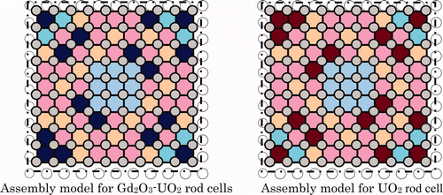
Figure 14. Deviation of calculated radial fission rates of MVP calculation with 157Gd-modified JENDL-3.3 from measurements for the test region of the Gd2O3-UO2 core.
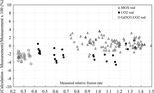
Figure 15. Deviation of calculated radial fission rates of CITATION-3D calculation from measurements for the 10 × 10 MOX assembly core.
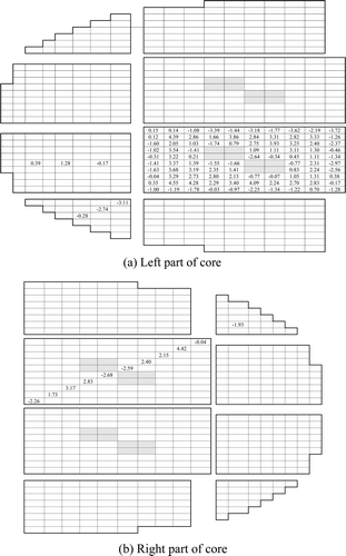
Figure 16. Deviation of calculated radial fission rates of THREEDANT calculation from measurements for the 10 × 10 MOX assembly core.
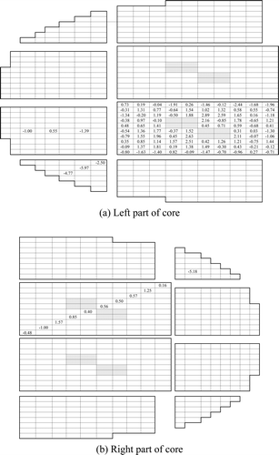
Figure 17. Comparison between calculated fission rates of CITATION-3D and measurements in the diagonal direction of the 10 × 10 MOX assembly core. Note: The average values of fission rates are normalized to 1.0.
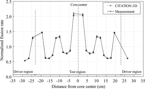
Figure A1. Measured relative radial fission rate distribution in the control blade core [Citation4]. Note: The average value of measured 81 fuel rods in the test region is 1.0 and that of 7 fuel rods in the driver region 1.0.
![Figure A1. Measured relative radial fission rate distribution in the control blade core [Citation4]. Note: The average value of measured 81 fuel rods in the test region is 1.0 and that of 7 fuel rods in the driver region 1.0.](/cms/asset/ab4132e5-cccf-4817-9d75-1bd18a2d6210/tnst_a_636553_o_f0018g.gif)
Figure A2. Measured relative radial fission rate distribution in the test region of the Gd2O3-UO2 rod core [Citation4]. Note: The average value of measured 167 fuel rods in the test region is 1.0.
![Figure A2. Measured relative radial fission rate distribution in the test region of the Gd2O3-UO2 rod core [Citation4]. Note: The average value of measured 167 fuel rods in the test region is 1.0.](/cms/asset/4c53a99a-2975-4338-98d0-de8c1cef97ba/tnst_a_636553_o_f0019g.gif)
Figure A3. Measured radial fission rate distribution in the 10 × 10 MOX assembly core [Citation4]. Note: The average value of measured 109 fuel rods in the test region is 1.0.
![Figure A3. Measured radial fission rate distribution in the 10 × 10 MOX assembly core [Citation4]. Note: The average value of measured 109 fuel rods in the test region is 1.0.](/cms/asset/a54c6e88-25a4-4e88-9b47-ff9f5fbb4959/tnst_a_636553_o_f0020g.gif)
