Figures & data
Figure 1. Visual feedback system. (a) Coordinate frames and (b) Perspective projection model.
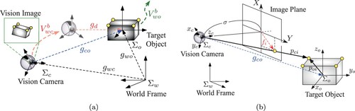
Figure 2. Block diagram of relative rigid body motion (RRBM) with camera model.
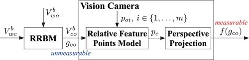
Figure 3. Block diagram of sampled visual motion observer.
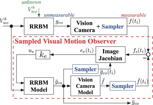
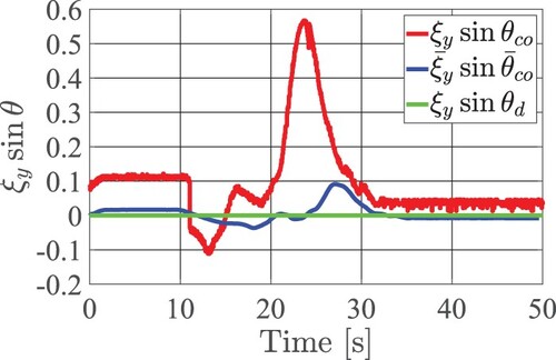
Figure 4. Image of time evolution of χ and η.
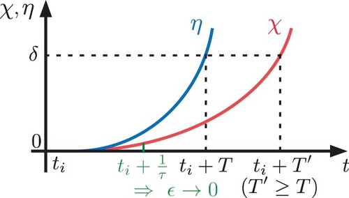
Figure 5. Block diagram of sampled visual feedback system.
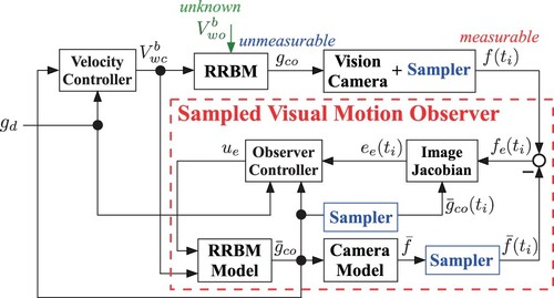
Figure 6. Potential function (simulation).
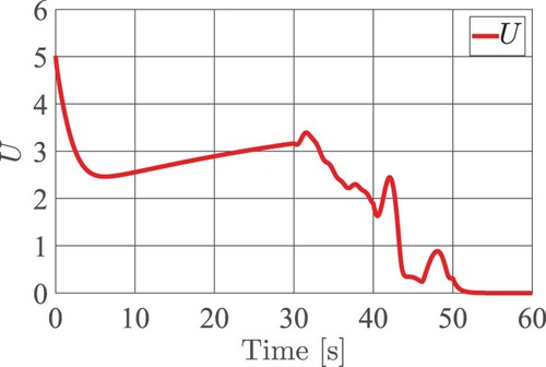
Figure 7. Norm of total error (simulation).
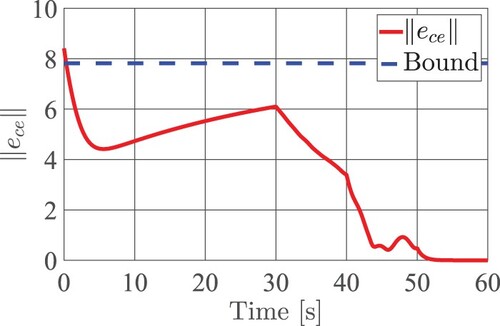
Figure 8. Experimental testbed.
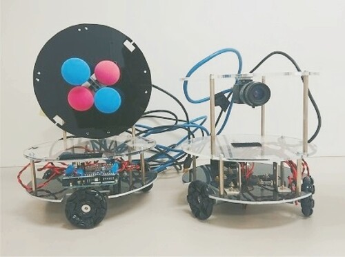
Figure 9. Potential function (experiment).
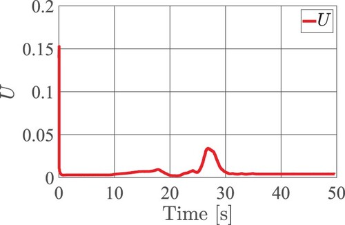
Figure 10. Norm of total error (experiment).
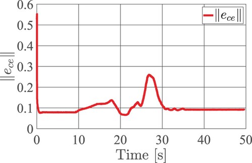
Figure 11. Velocity input command (experiment).
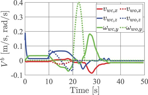
Figure 12. Relative position (experiment).
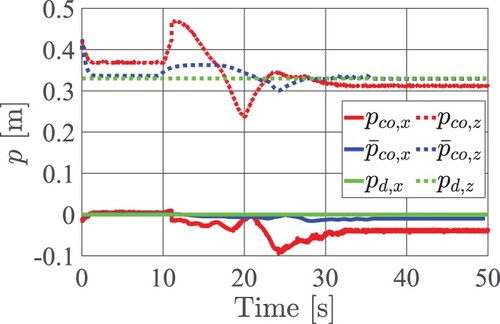
Figure 13. Relative orientation (experiment).