Figures & data
Figure 1. Sequence and 3D alignment of P-loops and inner helices in P-loop channels. A, Conventional sequence alignment. The top row shows universal labels.Citation3 P-loops of the TRPV channels are aligned as inCitation17 and in Nav1.4 and NavPaS channels they are aligned as in.Citation32 Gating-hinge residues (position i14) are underlined. Residues in position i20 and at the C-ends of the inner helices (positions i27 – i30 or i28 – i31) are boxed. Polar residues at the C-ends are red and predominantly hydrophobic residues, whose side chains may form H-bonds, are green. Note that in most of the sequences the inner-helix C-ends contain tetrads of polar-polar-hydrophobic-polar residues (motif p2hp). In the sodium, calcium, TRP and TPC channels, which have asparagines Ni20, are the p2hp motif is shifted vs. potassium channels, which have with leucines Li20. B and C, Side and extracellular views of the 3D aligned structures. The outer helices, P-loops and inner helices are green, blue and red, respectively. The 3D alignment was made by minimizing the RMS deviations of alpha carbons in the four P1 helices (positions p38 through p48) against respective positions in the Kv1.2 channel.
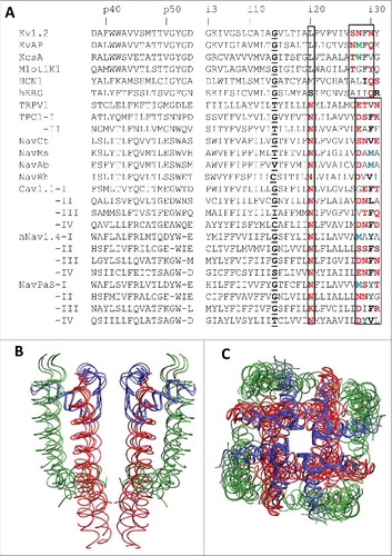
Figure 2. 3D Alignment and alpha carbon deviations in the inner helices. A, Inner helices in the closed channels MlotiK1, NavAb and KcsA. The channels are 3D aligned against the reference structure of the open Kv1.2 channel. Residues in positions i21, i20 and i29 (sticks) have the same orientations. Deviations of alpha carbons in the closed-state structures from the open-state Kv1.2 structure are small in positions i1 – i14 and steadily increase in positions i15 – i35, which are C-terminal to the gating-hinge residue. B, Inner helices in the open channels NavAb, NavMs and NavCt. The channels are 3D aligned against the reference structure of the open Kv1.2 channel. Residues in positions i21, i20 and i29 (sticks) have the same orientations. Deviations of the inner helix alpha carbons in the sodium channels from the open-state Kv1.2 are small in the N-halves of the helices. In the C-halves, the deviations increase (especially for the NavCt channel) due to variable aperture of the inner pore at the activation gate region. C, Deviations of the inner helix alpha carbons from the reference Kv1.2 structure for the NavRh channel calculated using the conventional (normal) sequence alignment () or an artificial alignment where the entire NavRh sequence is shifted one position right vs. Kv1.2. The shift results in large oscillations in the deviation plot. D, Intersubunit contacts between residues in positions Xi20 and (X-1)i29 in Kv1.2 and NavCt. Despite different nature and rather different mutual dispositions of the residues in positions i20 and i29, they have similar orientations and form open-state contacts Xi20: (X-1)i29.
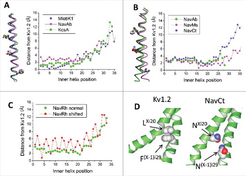
Figure 3. Inner helices in the open-state Kv1.2, TPC1 and TRPV1 channels. A, Tight intersubunit contacts are formed by pairs of hydrophobic residues LXi20: F(X-1)i29 in Kv1.2 and LXi21: F(X-1)i30 in TPC1. In the sequence alignment these pairs of residues are shifted by one position (). B, Inner helices in the 3D-aligned structures of Kv1.2 and TPC1. The residues participating in the open-state contact (Li20 and Fi29 in Kv1.2 and Li21 and Fi30 in TPC) have similar orientations despite they are in mismatching positions of the sequence alignment (). C, Inner helices in the 3D-aligned structures of NavCt and TRPV1. Residues in positions i20 and i29 have different orientations despite they are in matching positions of the sequence alignment (). D, The π-Helix bulge in the TRPV1 inner helix. A residue in position i16 is red. E, Deviations of the inner helix alpha carbons from the Kv1.2 structure in the TPC1 and TRPV1 channels. When the straightforward sequence alignment was used (), large oscillations in the deviation plot appeared C-terminal to position i16 (open circles). Correction of the alignment by shifting the TPC1 and TRPV1 sequences one position right vs. the Kv1.2 sequence eliminated the oscillations (filled circles). F, In the TRPV1 channel, the sidechains of asparagines Ni20 donate H-bonds to the backbone carbonyls i16; these H-bonds stabilize the π-helix bulges. G, Distances between the inner-helix backbone atoms Hi and Oi-4, which are expected to form H-bonds in regular alpha helices. The alpha-helical H-bonds are formed in all residues in NavMs, but in the TRPV1 channel the pattern of H-bonds is broken in the middle of the inner helix where the π-helix bulge appears.
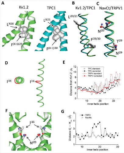
Figure 4. Alternative sequence alignments of the inner helices in P-loop channels. A, Corrected alignment in which asparagines in position i20 of sodium, calcium, TRPV and TPC channels are insertions vs. potassium channels. In this alignment, the boxed p2hp motifs (polar-polar-hydrophobic-polar residues) at the C-ends occur in matching positions. B, “Structure-based” sequence alignment corresponding to the 3D aligned structures in which all residues are in 3D-matching positions and form similar inter-subunit contacts that stabilize the open state. The insertions are placed in position i16, which forms a bulge in the TPC1 structure.
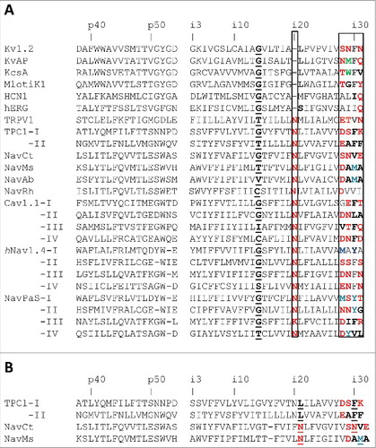
Figure 5. Models of artificial analogs of the TRPV1 channel. A, Comparison of the open-state structures of HCN1, TRPV1 and TRPV*, the artificial analogue of TRPV1 with the Ni20 deletion. Due to the helix bulge in TRPV1, residues MXi21 and V(X-1)i30 form a contact, which is similar to the contact between MXi20 with I(X-1)i29 in the HCN1 channel. Deletion of asparagine Ni20 in the TRPV* model caused disappearance of the bulge and appearance of contact MXi20: V(X-1)i29, which matches contact MXi20: V(X-1)i29 in HCN1. B, Comparison of the open-state structures of NavCt (left), TRPV1 (middle) and TRPV1**, the artificial analogue of TRPV1 with the twisted C-terminal thirds of the inner helices (right). In the NavCt and TRPV** channels, residues in positions Xi20 and (X-1)i29 form intersubunit open-state contacts. In the TRPV1 channel the inner helix has a π-helix bulge and respective contact is lacking. Imposing the alpha-helical conformations of the inner helices in the TRPV1** channel resulted in formation of the H-bond between NXi20 and T(X-1)i29.
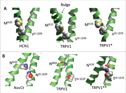
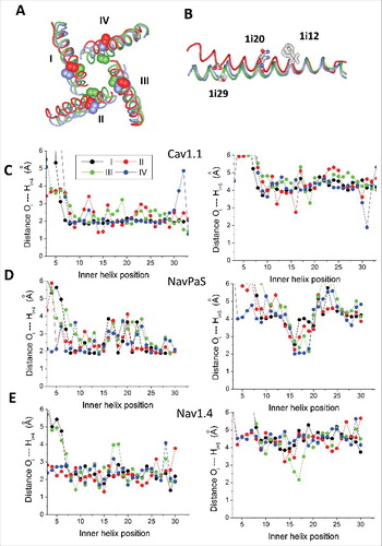
Figure 6. Different structures of the inner helices in Cav1.1, NavPaS and Nav1.4. A, Cytoplasmic view of the inner helices in the 3D-aligned Nav1.4 (blue), NavPaS (green) and Cav1.1 (red) channels. Space-filled are the Cα-Cβ bonds of asparagines Ni20. These bonds face the pore in NavPaS, but face away the pore axis in Cav1.1 and Nav1.4 (except for N3i20 in IIIS6). B, Side view at the superimposed helices IS6 of NavPaS, Nav1.4 and Cav1.1. The side chains in positions i12, i20 and i29 are shown. The side chains in position i12 have similar orientations, while orientations of residues in positions i20 and i29 are different. C-E, Distances between backbone atoms Oi and Hi+4 in the inner helices of Cav1.2 (C), NavPaS (D) and Nav1.4 (E). Data for repeats I, II, III, and IV are shown black, red, green and blue, respectively. In Cav1.1 (especially in repeat IV), most of the distances correspond to the classical alpha-helix. In NavPaS, but not in Cav1.1, the pattern of alpha-helical H-bonds is broken in the middle of S6. π-Helical H-bonds are formed in positions i15 – i20 of NavPaS, but not in Cav1.1. Characteristics of helical H-bonds of repeats I, II and IV in Nav1.4 are similar to those in Cav1.1, whereas in repeat III they are similar to those NavPaS (E).