1,201
Views
43
CrossRef citations to date
0
Altmetric
Original Articles

Harvesting heat energy from asphalt pavements: development of and comparison between numerical models and experiment

, &
Pages 159-169 | Received 30 Jun 2010, Accepted 21 Mar 2011, Published online: 19 Apr 2011

Figures & data

Figure 1 Slab with copper tube (a) experiment in progress, (b) compacted slab with pipes (without the top layer), (c) fixing of thermocouples on the compacted slab.
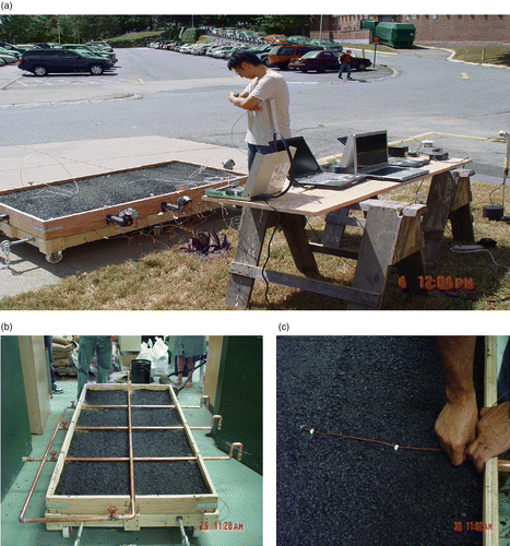
Figure 1 Slab with copper tube (a) experiment in progress, (b) compacted slab with pipes (without the top layer), (c) fixing of thermocouples on the compacted slab.

Figure 2 Copper tube frame inside slab and thermocouples on the slab (not to scale). Note: In this experiment, water was flown through only one of the three pipes – the one that is indicated by a blue filled circle.
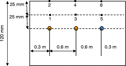
Figure 2 Copper tube frame inside slab and thermocouples on the slab (not to scale). Note: In this experiment, water was flown through only one of the three pipes – the one that is indicated by a blue filled circle.

Figure 3 Data for solar radiation versus time.

Figure 3 Data for solar radiation versus time.

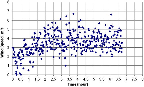
Figure 4 Data for wind speed versus time.

Figure 4 Data for wind speed versus time.

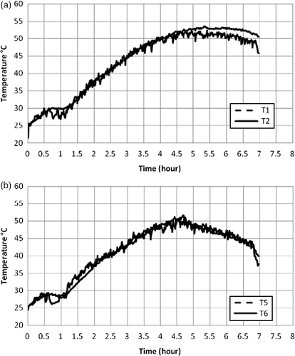
Figure 5 Plot of temperature versus time (a) no water flow, (b) water flow.

Figure 5 Plot of temperature versus time (a) no water flow, (b) water flow.

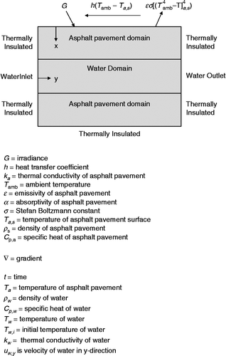
Figure 6 Theoretical considerations.

Figure 6 Theoretical considerations.

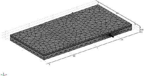
Figure 7 Details of the FE model.

Figure 7 Details of the FE model.

Figure 8 Solved model.

Figure 8 Solved model.

Table 1 Sequence of events.

Figure 9 Plots of temperature versus time for field (experimental) and FE (simulation) data (shaded area denotes 10% error bars around field values).
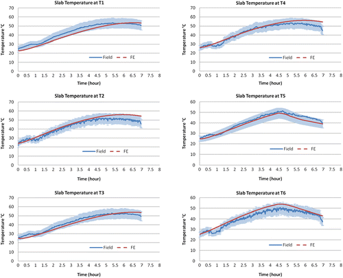
Figure 9 Plots of temperature versus time for field (experimental) and FE (simulation) data (shaded area denotes 10% error bars around field values).

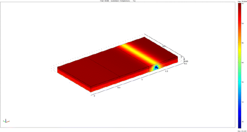
Figure 10 (a) Temperature distribution (6.4 mm diameter pipe with 1 l/min). (b) Temperature distribution (12.5 mm diameter pipe with 1 l/min). (c) Temperature distribution (19 mm diameter pipe with 1 l/min). (d) Temperature distribution (25 mm diameter pipe with 1 l/min).
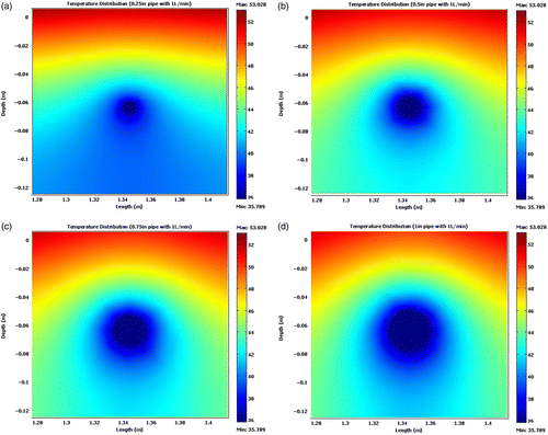
Figure 10 (a) Temperature distribution (6.4 mm diameter pipe with 1 l/min). (b) Temperature distribution (12.5 mm diameter pipe with 1 l/min). (c) Temperature distribution (19 mm diameter pipe with 1 l/min). (d) Temperature distribution (25 mm diameter pipe with 1 l/min).
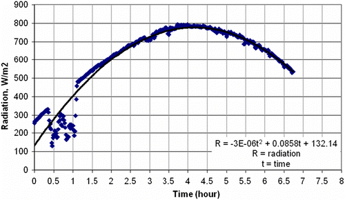
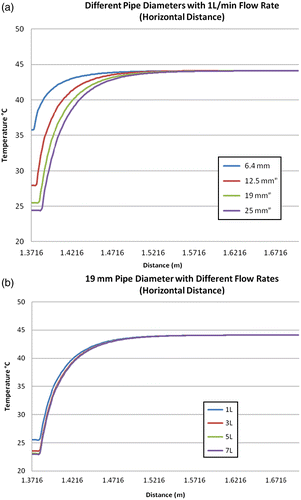
Figure 11 (a) Different pipe diameters with 1 l/min flow rate (horizontal distance). (b) 0.75″ pipe diameter with different flow rates (horizontal distance).

Figure 11 (a) Different pipe diameters with 1 l/min flow rate (horizontal distance). (b) 0.75″ pipe diameter with different flow rates (horizontal distance).

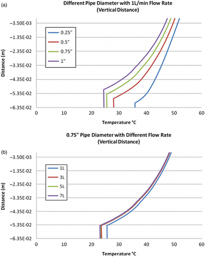
Figure 12 (a) Different pipe diameters with 1 l/min flow rate (vertical distance). (b) 0.75″ pipe diameter with different flow rates (vertical distance).

Figure 12 (a) Different pipe diameters with 1 l/min flow rate (vertical distance). (b) 0.75″ pipe diameter with different flow rates (vertical distance).

Reprints and Corporate Permissions

Please note: Selecting permissions does not provide access to the full text of the article, please see our help page How do I view content?

To request a reprint or corporate permissions for this article, please click on the relevant link below:

Academic Permissions

Please note: Selecting permissions does not provide access to the full text of the article, please see our help page How do I view content?

Obtain permissions instantly via Rightslink by clicking on the button below:

If you are unable to obtain permissions via Rightslink, please complete and submit this Permissions form. For more information, please visit our Permissions help page.