478
Views
7
CrossRef citations to date
0
Altmetric
Original Articles

Energy and exergy analysis of solar hybrid adsorption refrigeration system

&
Pages 289-300 | Received 08 Apr 2012, Accepted 01 Oct 2012, Published online: 15 Jan 2013

Figures & data

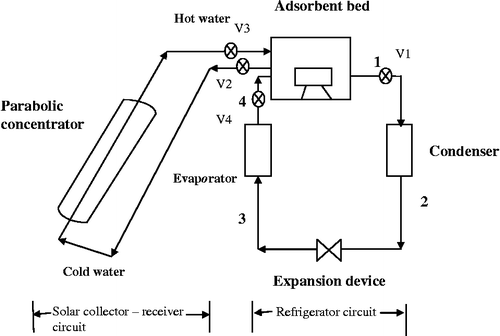
Figure 1 Schematic of the solar hybrid AR system.
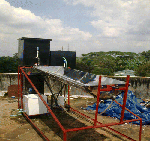
Figure 2 Photograph of the system.

Table 1 Specifications of the main components of the solar AR system.

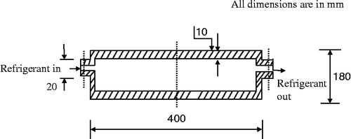
Figure 3 Cross-sectional view of adsorbent bed.

Table 2 The thermophysical properties of activated carbon.

Table 3 Uncertainty of performance parameters.

Table 4 Collector–receiver circuit.

Table 5 Refrigerator circuit.

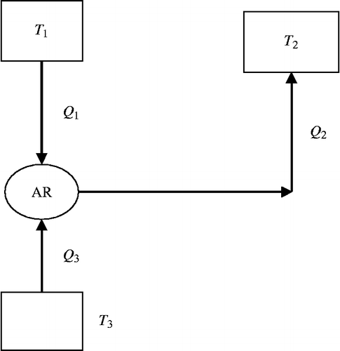
Figure 4 Thermodynamic equivalence of adsorption cycle.
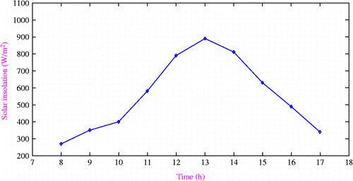
Figure 5 Variation of solar radiation with time.

Table 6 The average values of performance parameters of the solar hybrid AR system.

Table 7 Comparison of several typical studies by using activated carbon–methanol working pairs.

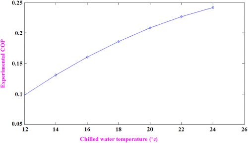
Figure 6 Variation of COP with increase in evaporator loads.
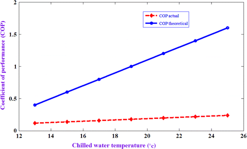
Figure 7 Variation of combined COP with increase in evaporator loads.
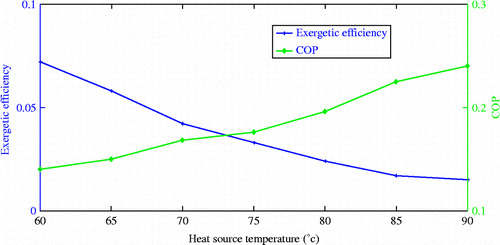
Figure 8 Effect of driving heat source temperature on exergetic efficiency and COP.
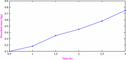
Figure 9 Variation of desorbed refrigerant with desorption time.
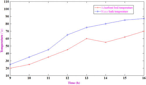
Figure 10 Variation of water and adsorbent temperature with heating time.
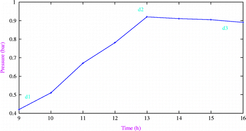
Figure 11 Pressure transients in adsorbent bed with heating and desorption time.

Table 8 Energy balance for the complete system.

Table 9 Second law analysis of refrigerator circuit.

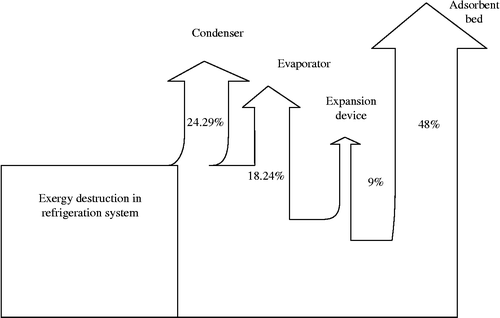
Figure 12 Grassmann (exergy flow) diagram for the solar AR system.

Table 10 Second law analysis of collector–receiver circuit.

Reprints and Corporate Permissions

Please note: Selecting permissions does not provide access to the full text of the article, please see our help page How do I view content?

To request a reprint or corporate permissions for this article, please click on the relevant link below:

Academic Permissions

Please note: Selecting permissions does not provide access to the full text of the article, please see our help page How do I view content?

Obtain permissions instantly via Rightslink by clicking on the button below:

If you are unable to obtain permissions via Rightslink, please complete and submit this Permissions form. For more information, please visit our Permissions help page.