393
Views
16
CrossRef citations to date
0
Altmetric
Article

Honge oil methyl ester and producer gas-fuelled dual-fuel engine operated with varying compression ratios

, , &
Pages 330-340 | Received 25 Feb 2013, Accepted 09 Aug 2013, Published online: 16 Oct 2013

Figures & data

Table 1 Properties of the fuels tested.

Table 2 Composition of the producer gas.

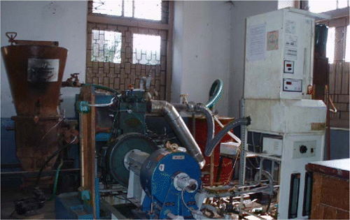
Figure 1 Experimental set-up.
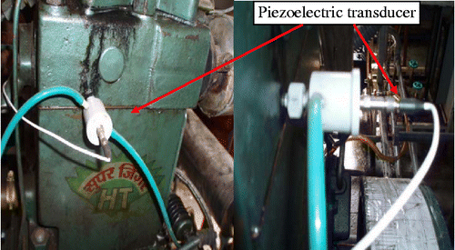
Figure 2 Views of the pressure sensor fitted to the engine cylinder.
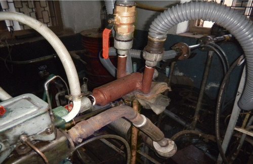
Figure 3 Parallel flow gas entry carburettor for producer gas induction fitted to the engine.

Table 3 Specifications of the engine.

Table 4 Specifications of the downdraft gasifier.

Table 5 Specifications of the piezoelectric transducer.

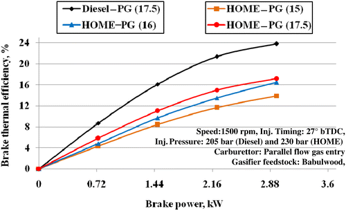
Figure 4 Variations in BTE with brake power.
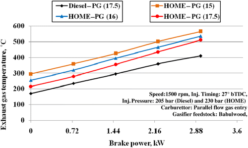
Figure 5 Variations in EGT with brake power.
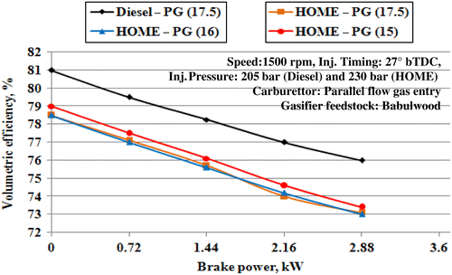
Figure 6 Variations in volumetric efficiency with brake power.
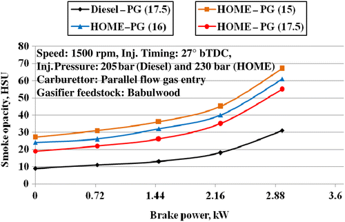
Figure 7 Variations in smoke opacity with brake power.
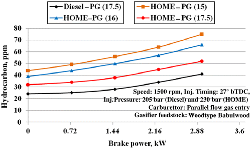
Figure 8 Variations in hydrocarbon emissions with brake power.
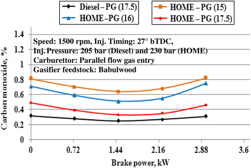
Figure 9 Variations in carbon monoxide with brake power.
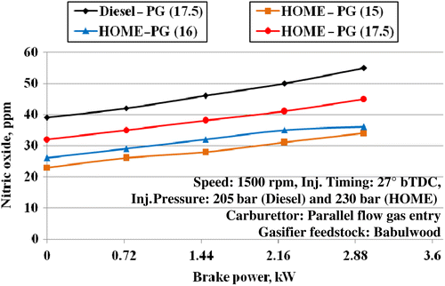
Figure 10 Variations in nitric oxide with brake power.
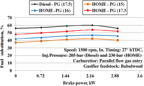
Figure 11 Variations in fuel substitution with brake power.
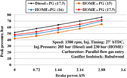
Figure 12 Variations in peak pressure with brake power.
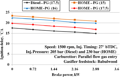
Figure 13 Variations in ignition delay with brake power.
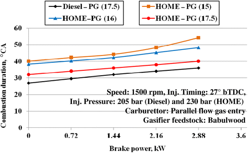
Figure 14 Variations in combustion duration with brake power.
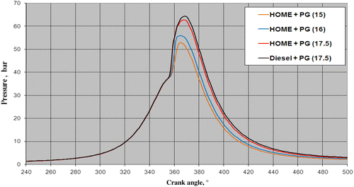
Figure 15 In-cylinder pressure versus crank angle at varying CRs for the HOME–producer gas combinations at the 80% load.
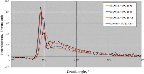
Figure 16 Rate of heat release versus crank angle at varying CRs for the HOME–producer gas combinations at the 80% load.

Reprints and Corporate Permissions

Please note: Selecting permissions does not provide access to the full text of the article, please see our help page How do I view content?

To request a reprint or corporate permissions for this article, please click on the relevant link below:

Academic Permissions

Please note: Selecting permissions does not provide access to the full text of the article, please see our help page How do I view content?

Obtain permissions instantly via Rightslink by clicking on the button below:

If you are unable to obtain permissions via Rightslink, please complete and submit this Permissions form. For more information, please visit our Permissions help page.