227
Views
8
CrossRef citations to date
0
Altmetric
Articles

Studies on the use of low-volatile non-edible oils in a thermal barrier-coated diesel engine

, &
Pages 341-351 | Received 19 Feb 2013, Accepted 23 Sep 2013, Published online: 07 Jan 2014

Figures & data

Table 1 Properties of the fuels used.
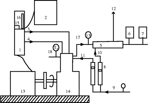
Figure 1 Overall view of the experimental setup with EGR arrangement. 1 – Control Panel, 2 – Computer system, 3 – Diesel flow line, 4 – Air flow line, 5 – Calorimeter, 6 – Exhaust gas analyzer, 7 – Smoke meter, 8 – Rota meter, 9, 11 – Inlet water temperature, 10 – Calorimeter inlet water temperature,12 – Calorimeter outlet water temperature, 13 – Dynamometer, 14 – CI Engine, 15 – Speed measurement,16 – Burette for fuel measurement, 17 – Exhaust gas outlet, 18 – Outlet water temperature, T1 – Inlet water temperature, T2 – Outlet water temperature, T3 – Exhaust gas temperature.

Table 2 Specifications of the engine.

Figure 2 Piston and cylinder head coated with PSZ.
Figure 3 Piston and cylinder head coated with Al2O3.
Figure 4 Effect of the variation in brake power on BTE.
Figure 5 Effect of the variation in brake power on smoke opacity.
Figure 6 Effect of the variation in brake power on HC emissions.
Figure 7 Effect of the variation in brake power on CO emissions.
Figure 8 Effect of the variation in brake power on NO x emissions.
Figure 9 Effect of the variation in brake power on ignition delay.
Figure 10 Effect of the variation in brake power on combustion duration.
Figure 11 Effect of the variation in cylinder pressure versus crank angle at an 80% load.
Figure 12 Effect of the variation in heat release rate with HnOME and COME at an 80% load.
Figure 13 Effect of the variation in brake power on BTE.
Figure 14 Effect of the variation in brake power on smoke opacity.
Figure 15 Effect of the variation in brake power on HC emissions.
Figure 16 Effect of the variation in brake power on CO emissions.
Figure 17 Effect of the variation in brake power on NO x emissions.
Figure 18 Effect of the variation in brake power on ignition delay.
Figure 19 Effect of the variation in brake power on combustion duration.
Figure 20 Effect of the variation in cylinder pressure versus crank angle at an 80% load.
Figure 21 Effect of the variation in heat release rate with HnOME and COME at an 80% load.

Reprints and Corporate Permissions

Please note: Selecting permissions does not provide access to the full text of the article, please see our help page How do I view content?

To request a reprint or corporate permissions for this article, please click on the relevant link below:

Academic Permissions

Please note: Selecting permissions does not provide access to the full text of the article, please see our help page How do I view content?

Obtain permissions instantly via Rightslink by clicking on the button below:

If you are unable to obtain permissions via Rightslink, please complete and submit this Permissions form. For more information, please visit our Permissions help page.