242
Views
1
CrossRef citations to date
0
Altmetric
Articles

Construction of evolving models for the environmental evaluation of innovative sub-systems based on a hierarchical agglomerative clustering

, &
Pages 386-404 | Received 27 Nov 2013, Accepted 25 Nov 2014, Published online: 27 Jan 2015

Figures & data

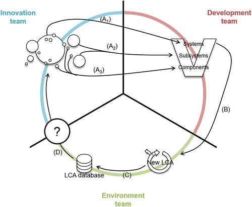
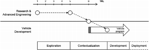
Figure 1 Simplified development and innovation process of a car manufacturer adapted from Beaume et al. (2009).
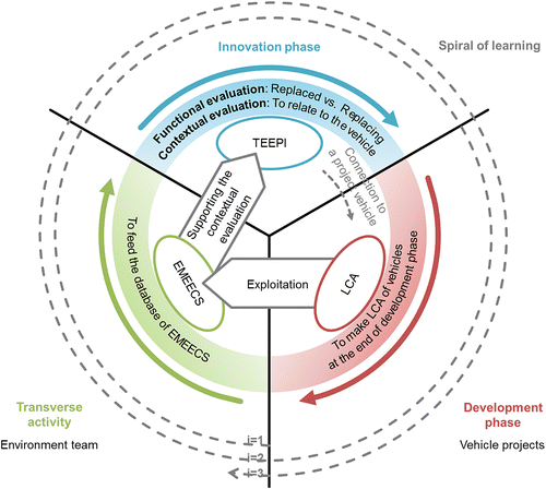
Figure 2 Schematic representation of the organizational context.
Figure 3 Schematic representation of the issue.

Table 1 List of available LCA results of cars.

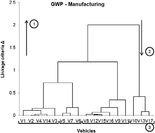
Figure 4 Dendrogram obtained for the manufacturing step and on the GWP indicator.

Table 2 Example of an expansion strategy in taking the Environment dimension into account.

Table 3 Environmental indicators communicated by car manufacturers.

Table 4 Environmental indicators and flows used in six publications from the automotive sector.

Table 5 Results for the four groups of dendrograms.
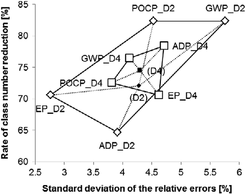
Figure 5 Representation of the rate of class number reduction as a function of the standard deviation of the relative errors of the environmental indicators taken separately of dendrogram groups (D2) and (D4).

Table 6 Description of the vehicles' clusters for the manufacturing step.
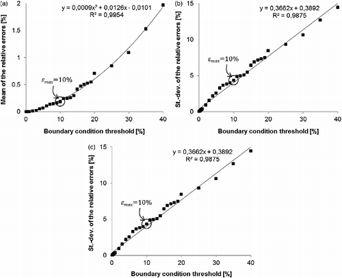
Figure 6 (a) Evolution of the mean of the relative errors as a function of the boundary condition (C) threshold of which value is varying between 0.1% and 40%. (b) Evolution of the standard deviation of the relative errors as a function of the boundary condition (C) threshold of which value is varying between 0.1% and 40%. (c) Evolution of the rate of class number reduction as a function of the boundary condition (C) threshold of which value is varying between 0.1% and 40%.
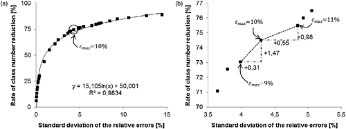
Figure 7 (a) Evolution of the rate of class number reduction as a function of the standard deviation of the relative errors for different values of the boundary condition (C) threshold varying between 0.1% and 40%. (b) Evolution of the rate of class number reduction as a function of the standard deviation of the relative errors for different values of the boundary condition (C) threshold varying between 7% and 13%.

Table 7 List of the omitted vehicles for the 10 simulations.
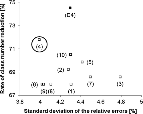
Figure 8 Representation of the rate of class reduction as a function of the standard deviation of the relative errors of 10 simulations with 13 vehicles compared with the results of the group (D4) with 17 vehicles.

Table 8 Description of the vehicles' clusters for the manufacturing step of the simulation (4).
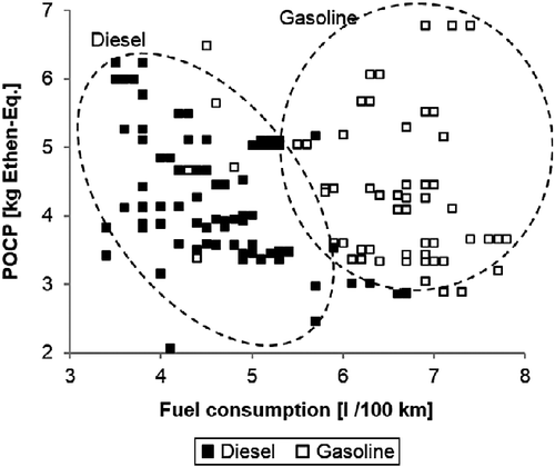
Figure 9 Value of the indicator POCP on the TtW step of 162 vehicles as a function of their fuel consumption and of the type of fuel (gasoline or diesel).

Appendix 1 Standard scores per life cycle step and for the full life cycle.

Appendix 2 Description of the clusters of vehicles.

Reprints and Corporate Permissions

Please note: Selecting permissions does not provide access to the full text of the article, please see our help page How do I view content?

To request a reprint or corporate permissions for this article, please click on the relevant link below:

Academic Permissions

Please note: Selecting permissions does not provide access to the full text of the article, please see our help page How do I view content?

Obtain permissions instantly via Rightslink by clicking on the button below:

If you are unable to obtain permissions via Rightslink, please complete and submit this Permissions form. For more information, please visit our Permissions help page.