526
Views
0
CrossRef citations to date
0
Altmetric
Articles

Development and modification of permanent magnet brushed DC motor for hybrid photovoltaic-operated solar systems

, , &
Pages 170-181 | Received 08 Sep 2013, Accepted 16 Sep 2014, Published online: 15 Sep 2015

Figures & data

Figure 1 Magnetic coupling arrangement in BLDC.
Figure 2 Arrangement of PMDC motor run by PV module coupled with a pump.
Figure 3 Modified permanent magnets arrangement in the stator.
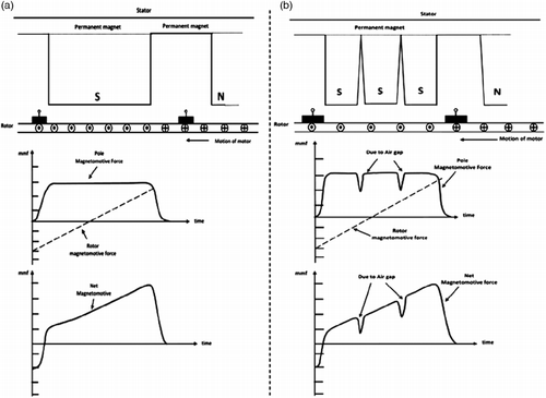
Figure 4 (a) Net magnetomotive force in case of a conventional PMDC motor; (b) Net magnetomotive force in case of a modified PMDC motor with reduced net emf.
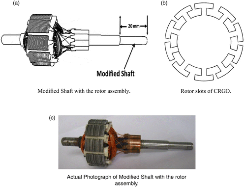
Figure 5 (a) Modified shaft with the rotor assembly; (b) Rotor slots of CRGO; (c) Actual photograph of modified shaft with the rotor assembly.
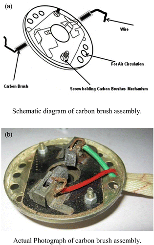
Figure 6 (a) Schematic diagram of carbon brush assembly; (b) Actual photograph of carbon brush assembly.
Figure 7 Rotor cage with the ventilating front and end covers.
Figure 8 Full schematic of the modified PMDC motor with pump.
Figure 9 Actual photograph of the modified PMDC motor.
Figure 10 Schematic diagram of hybrid PVT solar water.
Figure 11 Actual photograph of experimental Set-up.
Figure 12 No-load voltage versus RPM characteristics.
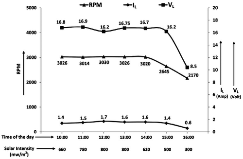
Figure 13 Load voltage VL and short circuit current IL versus RPM characteristics of modified motor on 05 October 2012.
Figure 14 Electrical power consumed versus water circulated in l/min with reference to solar intensity on 05 October 2012.
Figure 15 Instantaneous efficiency of hybrid PVT solar water heater in forced and natural circulation modes.

Reprints and Corporate Permissions

Please note: Selecting permissions does not provide access to the full text of the article, please see our help page How do I view content?

To request a reprint or corporate permissions for this article, please click on the relevant link below:

Academic Permissions

Please note: Selecting permissions does not provide access to the full text of the article, please see our help page How do I view content?

Obtain permissions instantly via Rightslink by clicking on the button below:

If you are unable to obtain permissions via Rightslink, please complete and submit this Permissions form. For more information, please visit our Permissions help page.