251
Views
2
CrossRef citations to date
0
Altmetric
Original Articles

Transforming submerged-arc welding slags into magnetic glass-ceramics

&
Pages 411-418 | Received 17 Jun 2014, Accepted 11 May 2016, Published online: 22 Jun 2016

Figures & data

Figure 1. Photograph of the slag welding flux generated during submerged-arc welding process.

Figure 1. Photograph of the slag welding flux generated during submerged-arc welding process.

Table 1. Chemical composition of the investigated SAWS (wt%).

Figure 2. XRD of the as-received slag welding flux. CaF2 (F); Mullite (M); Rutile (R); Al2O3 (Al); (Mn2O3)3MnSiO3 (B); Periclase (P); Quartz (Q); Cristobalite (C).
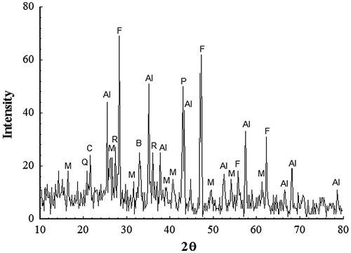
Figure 2. XRD of the as-received slag welding flux. CaF2 (F); Mullite (M); Rutile (R); Al2O3 (Al); (Mn2O3)3MnSiO3 (B); Periclase (P); Quartz (Q); Cristobalite (C).

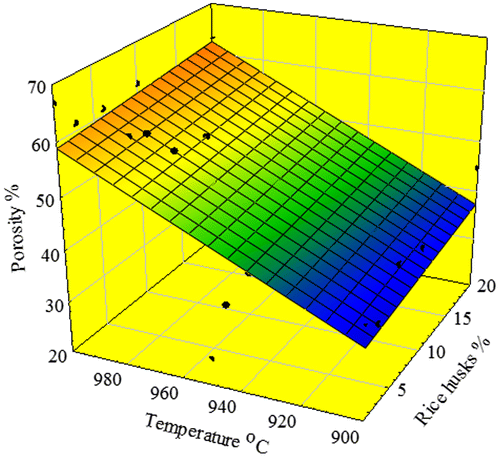
Figure 3. Variation in porosity with different RH percentages and temperatures.

Figure 3. Variation in porosity with different RH percentages and temperatures.

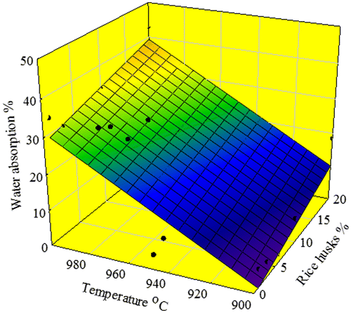
Figure 4. Variation in water absorption capacity with different RH percentages and temperatures.

Figure 4. Variation in water absorption capacity with different RH percentages and temperatures.

Figure 5. XRD patterns of powder samples of 1% RH sintered for 1 h at the indicated temperatures. D–diopside; J-jacobsite; C-corundum; M-MgAl2O4; P-pyrope; S-SiO2 Z-Ca1.82 Al3.64 Si0.36O8.
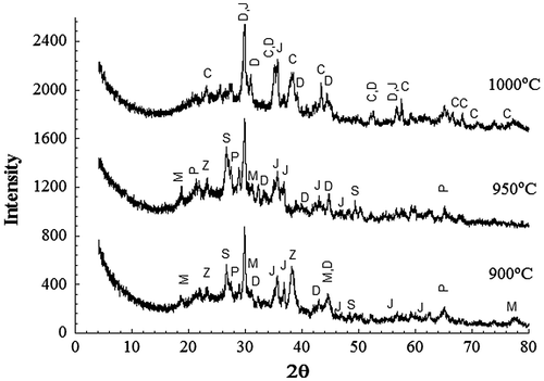
Figure 5. XRD patterns of powder samples of 1% RH sintered for 1 h at the indicated temperatures. D–diopside; J-jacobsite; C-corundum; M-MgAl2O4; P-pyrope; S-SiO2 Z-Ca1.82 Al3.64 Si0.36O8.

Figure 6. XRD patterns from powder samples of 20% RH sintered for 1 h at the indicated temperatures. D–diopside; J-jacobsite; C-corundum; M-MgAl2O4.
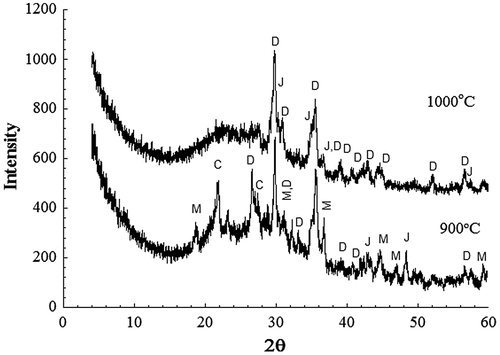
Figure 6. XRD patterns from powder samples of 20% RH sintered for 1 h at the indicated temperatures. D–diopside; J-jacobsite; C-corundum; M-MgAl2O4.

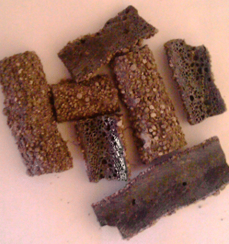
Figure 7. Image aspects of the porous glass–ceramic structures containing 20% RHs and sintered at various temperatures (a) 900 °C, (b) 975 °C, (c) 1000 °C and (d) 1000 °C at 6% RH.

Figure 7. Image aspects of the porous glass–ceramic structures containing 20% RHs and sintered at various temperatures (a) 900 °C, (b) 975 °C, (c) 1000 °C and (d) 1000 °C at 6% RH.

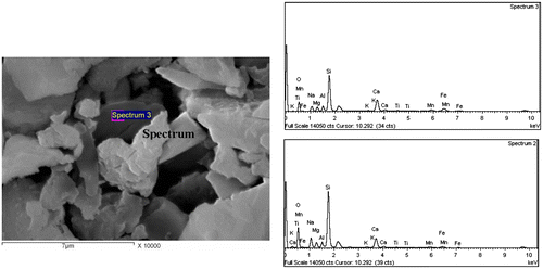
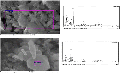
Figure 8. SEM of a sample sintered for 1 h with incorporation of 1% RH at 900 °C.

Figure 8. SEM of a sample sintered for 1 h with incorporation of 1% RH at 900 °C.

Figure 9. SEM of a sample sintered for 1 h with incorporation of 1% RH at 1000 °C.

Figure 9. SEM of a sample sintered for 1 h with incorporation of 1% RH at 1000 °C.

Table 2. Quantitative elemental composition of the crystals in Figure 8.

Table 3. Quantitative elemental composition of the crystals in Figure 9.

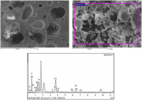
Figure 10. SEM of a sample sintered for 1 h with incorporation of 20% RH at 1000 °C.

Figure 10. SEM of a sample sintered for 1 h with incorporation of 20% RH at 1000 °C.

Figure 11. Magnetization curves of porous glass–ceramic containing 20% RH and sintered at 1000 °C for 1 h.
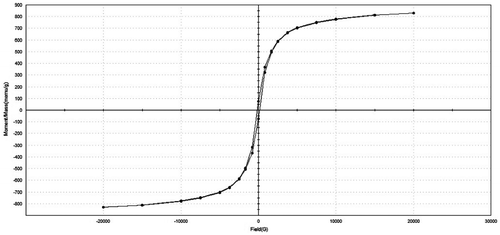
Figure 11. Magnetization curves of porous glass–ceramic containing 20% RH and sintered at 1000 °C for 1 h.

Table 4. Magnetic properties of the porous glass–ceramics. Ms, Mr and Hc are saturation magnetization, remanence and coercivity, respectively.

Reprints and Corporate Permissions

Please note: Selecting permissions does not provide access to the full text of the article, please see our help page How do I view content?

To request a reprint or corporate permissions for this article, please click on the relevant link below:

Academic Permissions

Please note: Selecting permissions does not provide access to the full text of the article, please see our help page How do I view content?

Obtain permissions instantly via Rightslink by clicking on the button below:

If you are unable to obtain permissions via Rightslink, please complete and submit this Permissions form. For more information, please visit our Permissions help page.