594
Views
4
CrossRef citations to date
0
Altmetric
Articles

Energy and exergy analysis of a PCM-based solar powered winter air conditioning using desiccant wheel during nocturnal

&
Pages 54-64 | Received 21 May 2016, Accepted 13 Jul 2017, Published online: 08 Sep 2017

Figures & data

Figure 1a. Schematic diagram of the phase change material (PCM)-based solar powered desiccant wheel air conditioning (SPDWAC) system represents the sensor position.
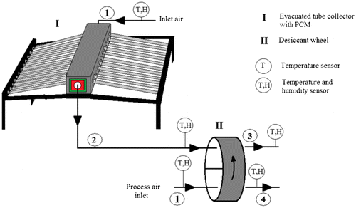
Figure 1a. Schematic diagram of the phase change material (PCM)-based solar powered desiccant wheel air conditioning (SPDWAC) system represents the sensor position.

Figure 1b. Photograph of the phase change material (PCM)-based solar powered desiccant wheel air conditioning (SPDWAC) system.
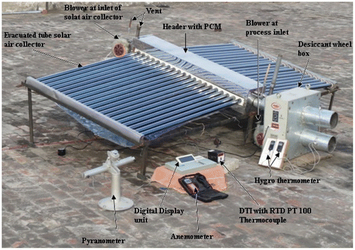
Figure 1b. Photograph of the phase change material (PCM)-based solar powered desiccant wheel air conditioning (SPDWAC) system.

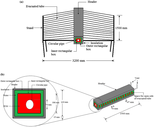
Figure 2. Schematic diagram of the evacuated tube solar air collector subsystem

Figure 2. Schematic diagram of the evacuated tube solar air collector subsystem

Figure 3. (a) Schematic diagrams of rotary desiccant wheel (b) Cross section of air flow channel with sinusoidal matrix
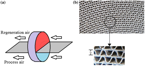
Figure 3. (a) Schematic diagrams of rotary desiccant wheel (b) Cross section of air flow channel with sinusoidal matrix

Table 1. Dimension and properties of DW [Yadav and Bajpai (Citation2012)].

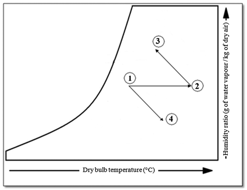
Figure 4. Psychrometric diagram of experimental set-up

Figure 4. Psychrometric diagram of experimental set-up

Table 2. Specification of the measuring instruments.

Figure 5. Variation of temperatures and solar intensity with time at a flow rate of 63.62 kg h−1 (27/02/2015)
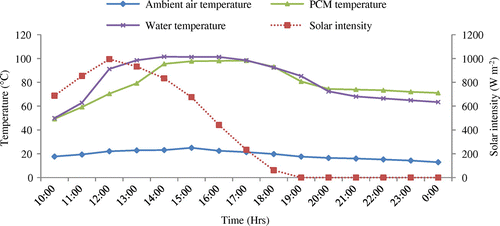
Figure 5. Variation of temperatures and solar intensity with time at a flow rate of 63.62 kg h−1 (27/02/2015)

Figure 6. Variation of regeneration rate, dehumidification rate and regeneration temperature with time for a flow rate of 63.62 kg h−1 (27/02/2015)
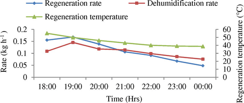
Figure 6. Variation of regeneration rate, dehumidification rate and regeneration temperature with time for a flow rate of 63.62 kg h−1 (27/02/2015)

Figure 7. Variation of regeneration effectiveness, dehumidification effectiveness and regeneration temperature with time for a flow rate of 63.62 kg h−1 (27/02/2015)
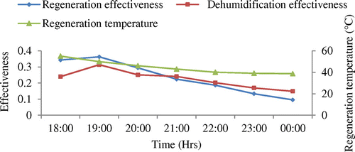
Figure 7. Variation of regeneration effectiveness, dehumidification effectiveness and regeneration temperature with time for a flow rate of 63.62 kg h−1 (27/02/2015)

Figure 8. Variation of thermal effectiveness and regeneration temperature with time for a flow rate of 63.62 kg h−1(27/02/2015)
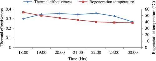
Figure 8. Variation of thermal effectiveness and regeneration temperature with time for a flow rate of 63.62 kg h−1(27/02/2015)

Figure 9. Variation of thermal coefficient of performance of the system and heating capacity with time for a flow rate of 63.62 kg h−1(27/02/2015)
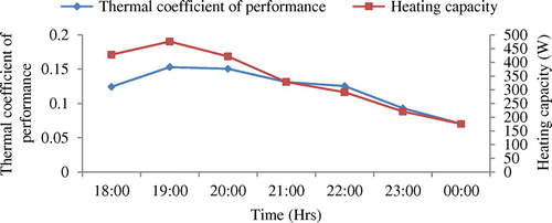
Figure 9. Variation of thermal coefficient of performance of the system and heating capacity with time for a flow rate of 63.62 kg h−1(27/02/2015)

Figure 10. Variation of exergy efficiency of the system and exergy heating capacity with time for a flow rate of 63.62 kg h−1 (27/02/2015)
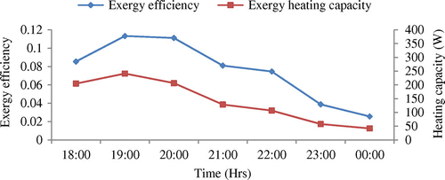
Figure 10. Variation of exergy efficiency of the system and exergy heating capacity with time for a flow rate of 63.62 kg h−1 (27/02/2015)

Figure 11. Variation of temperatures and solar intensity with time for a flow rate of 127.23 kg h−1 (04/03/2015)
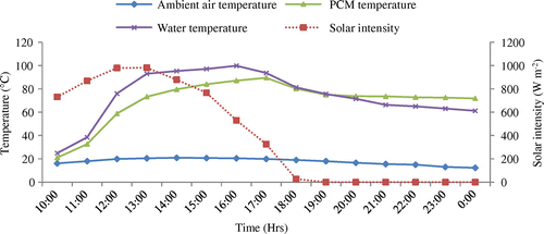
Figure 11. Variation of temperatures and solar intensity with time for a flow rate of 127.23 kg h−1 (04/03/2015)

Figure 12. Variation of regeneration rate, dehumidification rate and regeneration temperature with time for a flow rate of 127.23 kg h−1 (04/03/2015)
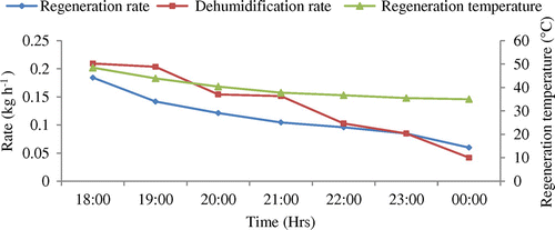
Figure 12. Variation of regeneration rate, dehumidification rate and regeneration temperature with time for a flow rate of 127.23 kg h−1 (04/03/2015)

Figure 13. Variation of regeneration effectiveness, dehumidification effectiveness and regeneration temperature with time for a flow rate of 127.23 kg h−1 (04/03/2015)
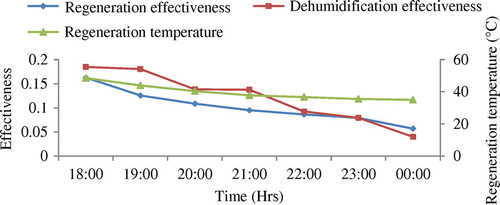
Figure 13. Variation of regeneration effectiveness, dehumidification effectiveness and regeneration temperature with time for a flow rate of 127.23 kg h−1 (04/03/2015)
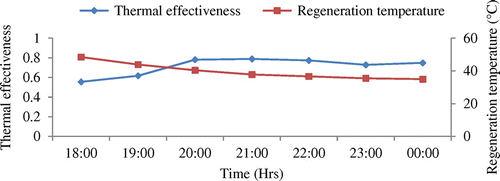
Figure 14. Variation of thermal effectiveness and regeneration temperature with time for a flow rate of 127.23 kg h−1 (04/03/2015)

Figure 14. Variation of thermal effectiveness and regeneration temperature with time for a flow rate of 127.23 kg h−1 (04/03/2015)

Figure 15. Variation of thermal coefficient of performance of the system and heating capacity with time for a flow rate of 127.23 kg h−1 (04/03/2015)
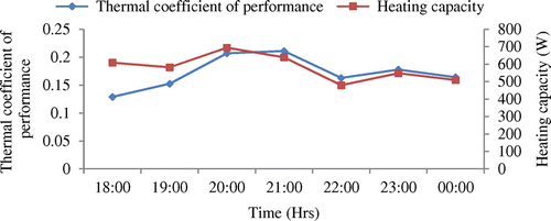
Figure 15. Variation of thermal coefficient of performance of the system and heating capacity with time for a flow rate of 127.23 kg h−1 (04/03/2015)

Figure 16. Variation of exergy efficiency of the system and exergy heating effect with time for a flow rate of 127.23 kg h−1 (04/03/2015)
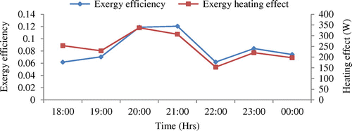
Figure 16. Variation of exergy efficiency of the system and exergy heating effect with time for a flow rate of 127.23 kg h−1 (04/03/2015)

Table 3. Performance analysis of PCM-based SPDWAC.

Reprints and Corporate Permissions

Please note: Selecting permissions does not provide access to the full text of the article, please see our help page How do I view content?

To request a reprint or corporate permissions for this article, please click on the relevant link below:

Academic Permissions

Please note: Selecting permissions does not provide access to the full text of the article, please see our help page How do I view content?

Obtain permissions instantly via Rightslink by clicking on the button below:

If you are unable to obtain permissions via Rightslink, please complete and submit this Permissions form. For more information, please visit our Permissions help page.