871
Views
4
CrossRef citations to date
0
Altmetric
Articles

Power management for hybrid distributed generation systems

, &
Pages 65-74 | Received 23 Aug 2016, Accepted 25 Sep 2017, Published online: 12 Oct 2017

Figures & data

Figure 1. Daily load duration curve.

Figure 1. Daily load duration curve.

Table 1. Sizing of system components.

Table 2. Specifications of system components.

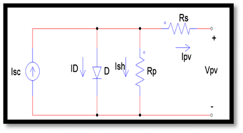
Figure 2. Equivalent Circuit of a Single Solar Cell.

Figure 2. Equivalent Circuit of a Single Solar Cell.

Figure 3. Simulink model of PV subsystem (a) and simulation results (b) AC current, AC voltage and (d) Total power.
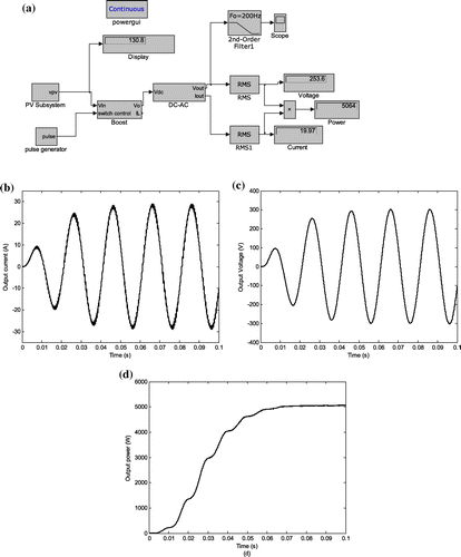
Figure 3. Simulink model of PV subsystem (a) and simulation results (b) AC current, AC voltage and (d) Total power.

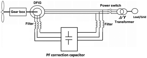
Figure 4. Wind energy subsystem.

Figure 4. Wind energy subsystem.

Figure 5. (a) Equivalent circuit of a DFIG and (b) Equivalent circuit of a DFIG viewed from the rotor side.
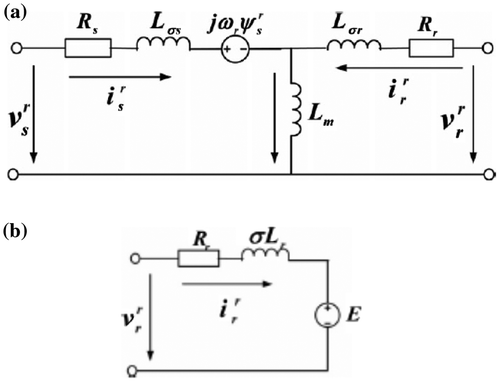
Figure 5. (a) Equivalent circuit of a DFIG and (b) Equivalent circuit of a DFIG viewed from the rotor side.

Figure 6. Simulink model of Wind energy subsystem (a), Simulation results (b) Phase current (c) Phase voltage.
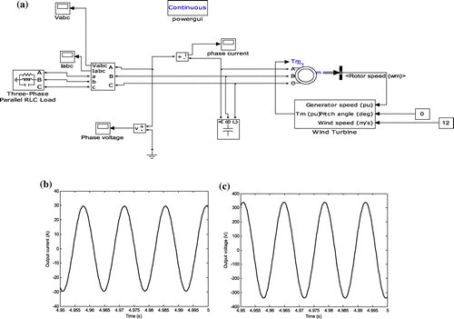
Figure 6. Simulink model of Wind energy subsystem (a), Simulation results (b) Phase current (c) Phase voltage.

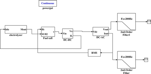
Figure 7. Simulink model of FC and electrolyser energy subsystem.

Figure 7. Simulink model of FC and electrolyser energy subsystem.

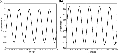
Figure 8. Simulation results of FC subsystem: (a) Output current (b) Output voltage.

Figure 8. Simulation results of FC subsystem: (a) Output current (b) Output voltage.

Figure 9. Simulink model of Battery-bank subsystem (a), and simulation results for output current (b) and output voltage (c).
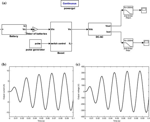
Figure 9. Simulink model of Battery-bank subsystem (a), and simulation results for output current (b) and output voltage (c).
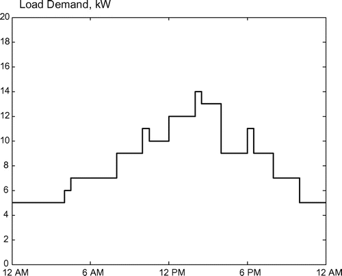
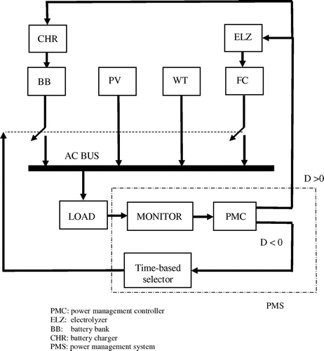
Figure 10. Block diagram of the overall power management system.

Figure 10. Block diagram of the overall power management system.

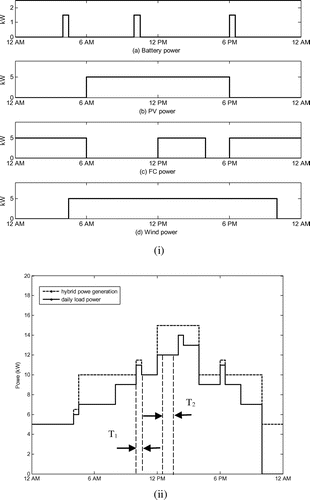
Figure 11. Power generated from each energy source of the DG system (i) and the daily load power and hybrid power generation (ii).

Figure 11. Power generated from each energy source of the DG system (i) and the daily load power and hybrid power generation (ii).

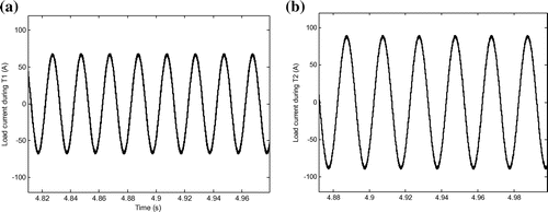
Figure 12. Waveform of the total load current: (a) during the period T1, (b) during the period T2.

Figure 12. Waveform of the total load current: (a) during the period T1, (b) during the period T2.

Reprints and Corporate Permissions

Please note: Selecting permissions does not provide access to the full text of the article, please see our help page How do I view content?

To request a reprint or corporate permissions for this article, please click on the relevant link below:

Academic Permissions

Please note: Selecting permissions does not provide access to the full text of the article, please see our help page How do I view content?

Obtain permissions instantly via Rightslink by clicking on the button below:

If you are unable to obtain permissions via Rightslink, please complete and submit this Permissions form. For more information, please visit our Permissions help page.