931
Views
16
CrossRef citations to date
0
Altmetric
Case Report

Challenges for modelling and integrating environmental performances in concept design: the case of an automotive component lightweighting

, , , , ORCID Icon &
Pages 135-148 | Received 04 Jul 2017, Accepted 05 Dec 2017, Published online: 04 Jan 2018

Figures & data

Figure 1. Workflow and data exchange within the eco-design approach for a component re-design.

Figure 1. Workflow and data exchange within the eco-design approach for a component re-design.

Table 1. List of TB parts, materials and masses for the current solution (aluminium alloy housing TB) and the new one (PETGF housing TB).

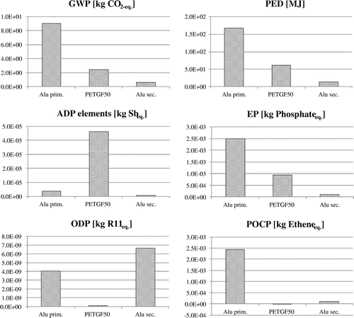
Figure 2. Environmental assessment comparison of alternative materials for the TB housing.

Figure 2. Environmental assessment comparison of alternative materials for the TB housing.

Figure 3. Exploded view of the current TB solution (aluminium alloy housing TB) and the new one (PETGF housing TB).
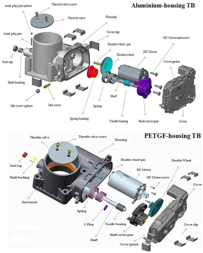
Figure 3. Exploded view of the current TB solution (aluminium alloy housing TB) and the new one (PETGF housing TB).

Figure 4. Details about minor design modifications due to the new housing material: co-moulded metallic duct insert in the PETGF-housing TB (a); idle screw and idle screw sphere in the Aluminium housing TB (b – Before) and PETGF-housing TB (b – After).
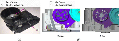
Figure 4. Details about minor design modifications due to the new housing material: co-moulded metallic duct insert in the PETGF-housing TB (a); idle screw and idle screw sphere in the Aluminium housing TB (b – Before) and PETGF-housing TB (b – After).
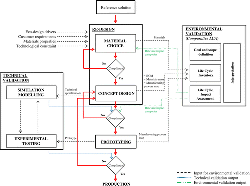
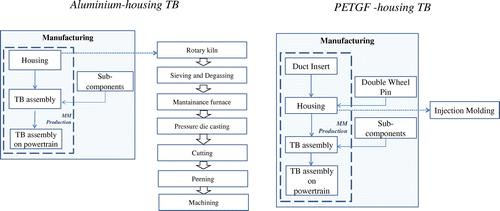
Figure 5. Manufacturing process map of Aluminium housing TB and PETGF-housing TB.

Figure 5. Manufacturing process map of Aluminium housing TB and PETGF-housing TB.

Table 2. Schematisation of TB LC stages and related processes included in the analysis (F = foreground process; B = background process).

Table 3. Input and output flow measured for the housing manufacturing technologies.

Table 4. Use stage modelling: equations and data.

Table 5. LCIA results for aluminium housing TB and PETGF-housing TB.

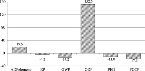
Figure 6. Impact of PETGF-housing TB with respect to aluminium alloy housing TB (%).

Figure 6. Impact of PETGF-housing TB with respect to aluminium alloy housing TB (%).

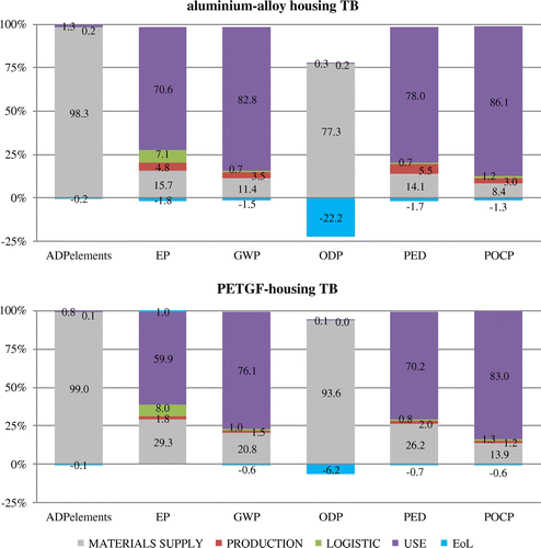
Figure 7. Contribution analysis by LC stage of impacts for aluminium alloy housing TB and PETGF-housing TB.

Figure 7. Contribution analysis by LC stage of impacts for aluminium alloy housing TB and PETGF-housing TB.

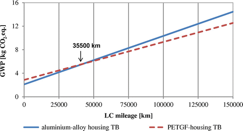
Figure 8. Break-even analysis based on vehicle mileage for GWP.

Figure 8. Break-even analysis based on vehicle mileage for GWP.

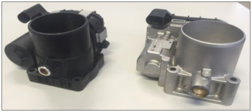
Figure 9. Prototypes of aluminium alloy housing (right hand) and PETGF housing (left hand).

Figure 9. Prototypes of aluminium alloy housing (right hand) and PETGF housing (left hand).
Supplemental material

Delogu_M_Supplemental_material.docx

Download MS Word (36.3 KB)

Reprints and Corporate Permissions

Please note: Selecting permissions does not provide access to the full text of the article, please see our help page How do I view content?

To request a reprint or corporate permissions for this article, please click on the relevant link below:

Academic Permissions

Please note: Selecting permissions does not provide access to the full text of the article, please see our help page How do I view content?

Obtain permissions instantly via Rightslink by clicking on the button below:

If you are unable to obtain permissions via Rightslink, please complete and submit this Permissions form. For more information, please visit our Permissions help page.