482
Views
0
CrossRef citations to date
0
Altmetric
Article

H loop-shaping controller design for a grid-connected single-phase photovoltaic system

ORCID Icon &
Pages 196-204 | Received 19 Oct 2016, Accepted 13 Feb 2018, Published online: 12 Mar 2018

Figures & data

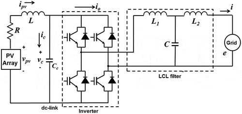
Figure 1. Equivalent circuit diagram of a grid-connected single-phase PV system.

Figure 1. Equivalent circuit diagram of a grid-connected single-phase PV system.

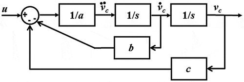
Figure 2. Block diagram of the grid-connected single-phase PV system.

Figure 2. Block diagram of the grid-connected single-phase PV system.

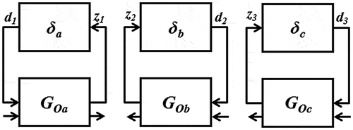
Figure 3. LFT representations of the uncertainty parameters.

Figure 3. LFT representations of the uncertainty parameters.

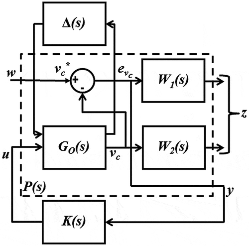
Figure 4. Proposed H loop-shaping control configuration.

Figure 4. Proposed H∞ loop-shaping control configuration.

Figure 5. Achievement of Criterion 1: (a) Singular value of the closed loop of the grid-connected single-phase PV system and (b) Singular values of S(s) and 1/W 1(s).
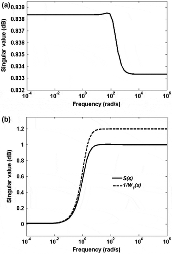
Figure 5. Achievement of Criterion 1: (a) Singular value of the closed loop of the grid-connected single-phase PV system and (b) Singular values of S(s) and 1/W 1(s).

Figure 6. Achievement of Criterion 2: (a) Singular values of W 2(s) and the worst-case profile of uncertainty and (b) Robust performance of the controller.
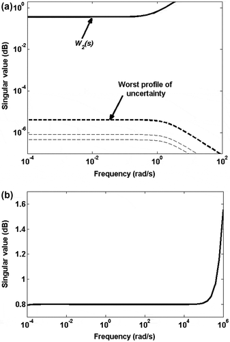
Figure 6. Achievement of Criterion 2: (a) Singular values of W 2(s) and the worst-case profile of uncertainty and (b) Robust performance of the controller.

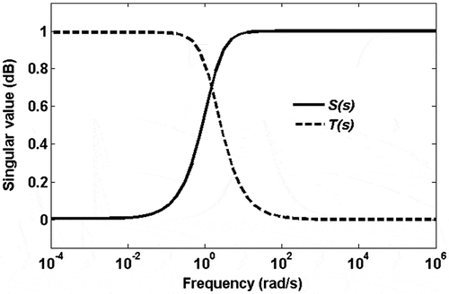
Figure 7. Achievement of Criterion 3: Singular values of S(s) and T(s).

Figure 7. Achievement of Criterion 3: Singular values of S(s) and T(s).

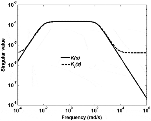
Figure 8. Singular values of the original controller K(s) and the reduced order controller K r (s).

Figure 8. Singular values of the original controller K(s) and the reduced order controller K r (s).

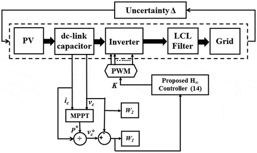
Figure 9. Implementation block diagram of the proposed controller.

Figure 9. Implementation block diagram of the proposed controller.

Table 1. Grid-connected single-phase PV system parameters.

Figure 10. Response from grid-connected single-phase PV system during standard atmospheric condition: (a) output dc power (in Watt) and (b) grid voltage (in Volt) [dashed line] and grid current (in Ampere) [solid line].

Figure 10. Response from grid-connected single-phase PV system during standard atmospheric condition: (a) output dc power (in Watt) and (b) grid voltage (in Volt) [dashed line] and grid current (in Ampere) [solid line].

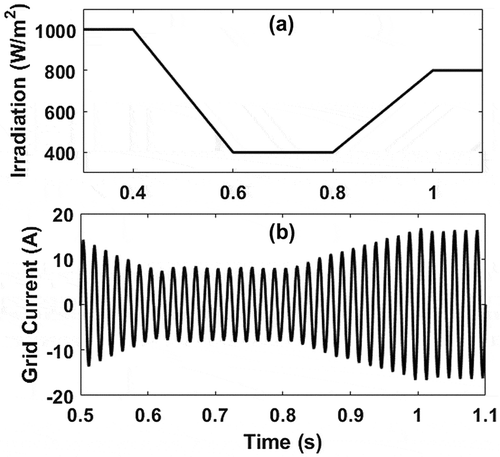
Figure 11. Grid current flow from grid-connected single-phase PV system during changing atmospheric condition: (a) solar irradiation and (b) grid current.

Figure 11. Grid current flow from grid-connected single-phase PV system during changing atmospheric condition: (a) solar irradiation and (b) grid current.

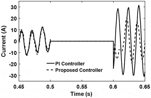
Figure 12. Grid current flow from grid-connected single-phase PV system during fault condition.

Figure 12. Grid current flow from grid-connected single-phase PV system during fault condition.

Reprints and Corporate Permissions

Please note: Selecting permissions does not provide access to the full text of the article, please see our help page How do I view content?

To request a reprint or corporate permissions for this article, please click on the relevant link below:

Academic Permissions

Please note: Selecting permissions does not provide access to the full text of the article, please see our help page How do I view content?

Obtain permissions instantly via Rightslink by clicking on the button below:

If you are unable to obtain permissions via Rightslink, please complete and submit this Permissions form. For more information, please visit our Permissions help page.