Figures & data
Figure 1. Waste plastics collected.
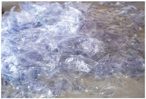
Figure 2. Pyrolysis equipment.
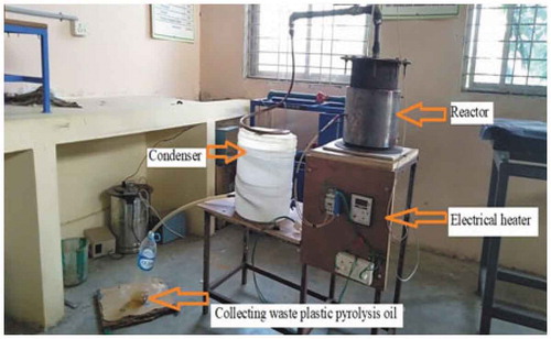
Figure 3. Photographical view of the experimental setup.
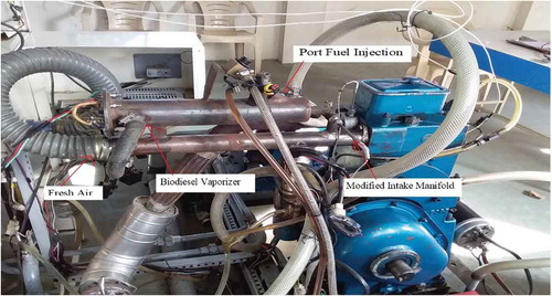
Figure 4. Schematic diagram of the experimental setup.
Figure 5. Schematic diagram of biodiesel fuel vaporiser.
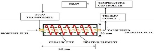
Figure 6. Photo graphical view of ECU.
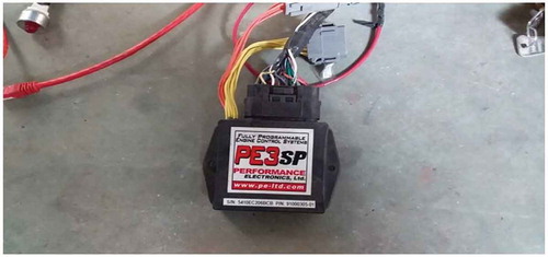
Table 1. Properties of diesel and waste plastic pyrolysis oil.
Table 2. Experimental engine specifications.
Table 3. Fuel vaporiser specification.
Figure 7. Variation of cylinder pressure with crank angle.
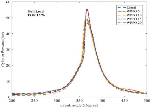
Figure 8. Variation of rate of heat release with crank angle.
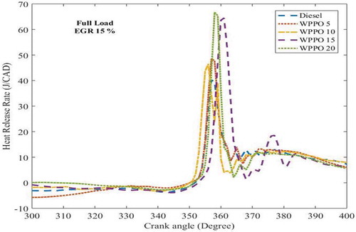
Figure 9. Variation of rate of pressure rise with crank angle.
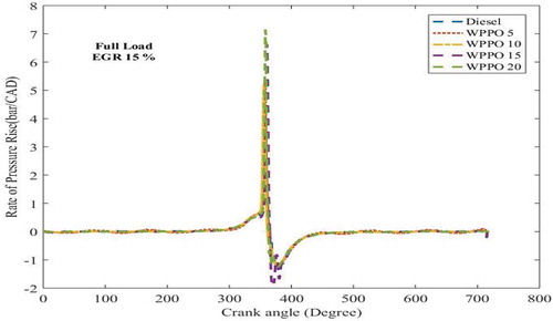
Figure 10. (a–e) BTE of diesel and waste plastic pyrolysis oil biodiesel HCCI combustion at different load and EGR conditions.
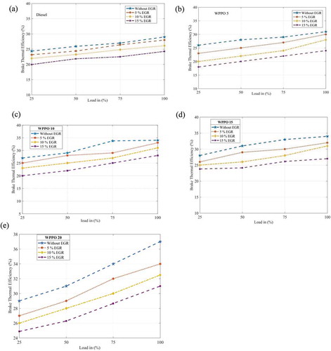
Figure 11. (a–e) EGT of diesel and waste plastic pyrolysis oil biodiesel HCCI combustion at various load and EGR conditions.
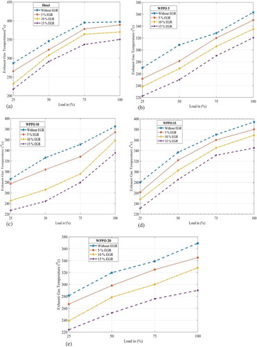
Figure 12. (a–e) NOx emissions of diesel and waste plastic pyrolysis oil biodiesel HCCI combustion at varying load and EGR percentages.
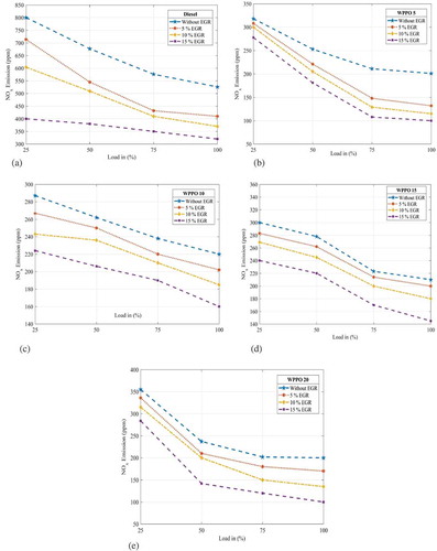
Figure 13. (a–e) CO emissions of diesel and waste plastic pyrolysis oil biodiesel HCCI combustion at varying load and EGR percentages.
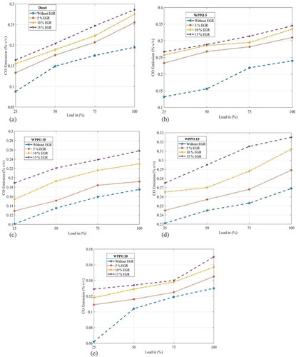
Figure 14. (a–e) UHC emissions of diesel and waste plastic pyrolysis oil biodiesel HCCI combustion at different load and EGR percentages.
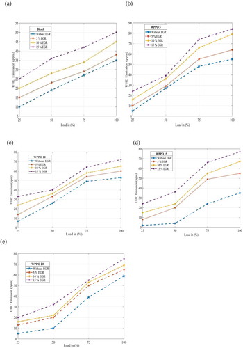
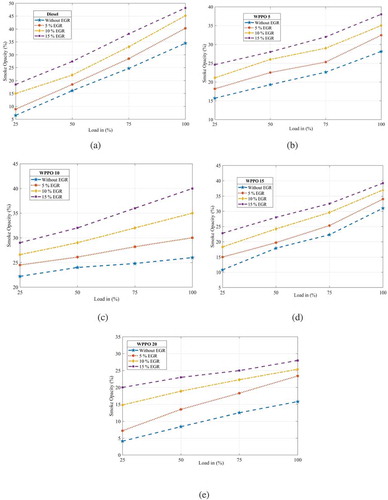
Figure 15. (a–e) Smoke opacity of diesel and waste plastic pyrolysis oil biodiesel HCCI combustion at different load and EGR conditions.