Figures & data
Figure 1. Topology of PV-Grid Integration System.
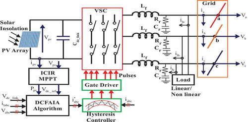
Figure 2. Detail Structure of DCFAIA Control Scheme.
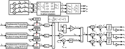
Figure 3. Ppv -Vpv characteristic showing increment and decrement of Vpv.
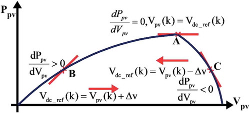
Figure 4. Structure showing fundamental extraction of ia using DCFAIA.
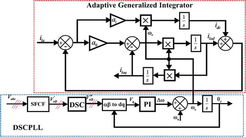
Figure 5. Basic Structure of Stationary Frame Complex Filter.
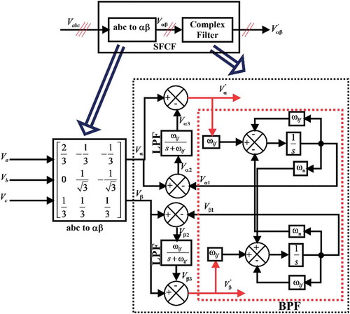
Figure 6. Bode Magnitude plot of Band Pass Filter and Complex Filter.
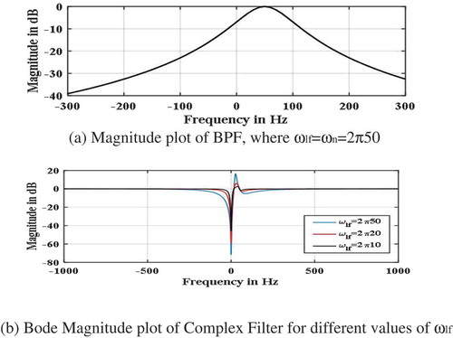
Figure 7. Response of Vabc, phase, and frequency with a phase jump of – 40◦.
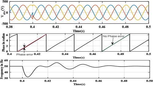
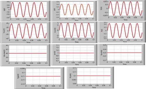
Figure 8. Performance analysis of the GIPVS under-balanced linear load.
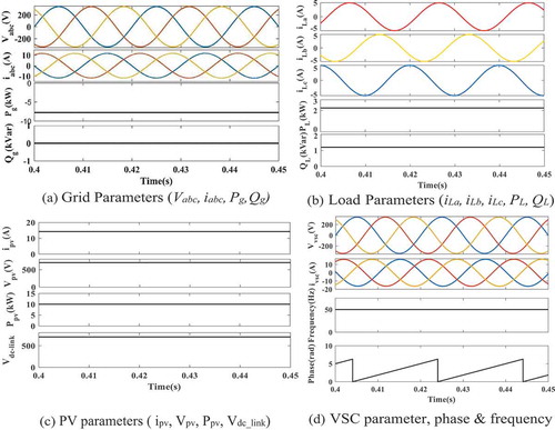
Figure 9. Performance analysis of the GIPVS under nonlinear load.
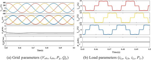
Figure 10. Transient performances of the GIPV system under-unbalanced nonlinear load.
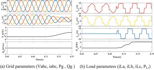
Figure 11. Performance of GIPVS under variation of solar irradiance.

Figure 12. Performance of GIPVS with phase angle jump of – 40◦.
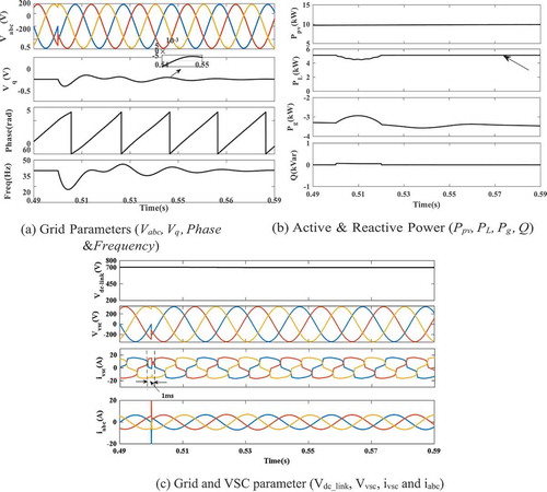
Figure 13. Performance of GIPVS with step change in frequency of +3 Hz.
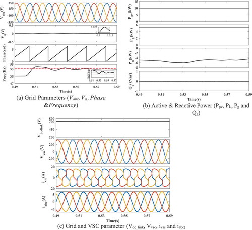
Figure 14. Performance of GIPVS under voltage sag.
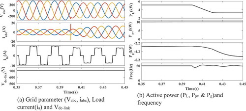
Figure 15. Performance of GIPVS under-voltage swell.
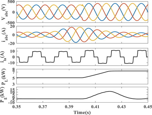
Figure 16. Frequency tracking capability between TOGI-FLL and DCFAIA.
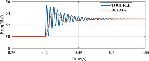
Figure 17. Comparative response of average active weight component/average load current (ilavg) between LMF, DNLMS, DCFAIA, and SRFPLL Algorithm.
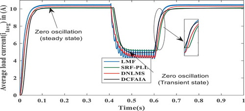
Table 1. Comparative result analysis of LMF, DNLMS, SRF-PLL and DCFAIA.
Figure 18. Harmonic Analysis of Performance Parameters.
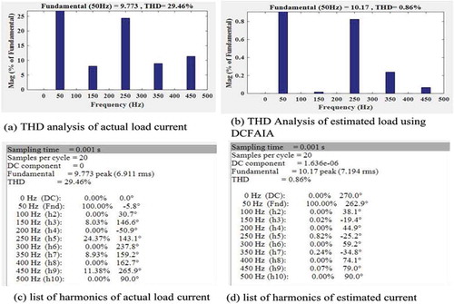
Figure 19. Prototype model of 1-ph Grid Integrated PV System.
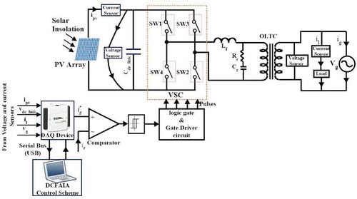
Figure 20. Experimental setup of Grid Integrated PV system.
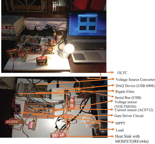
Figure 21. Performance parameters of prototype model under-balanced load.