Figures & data
Table 1. System parameters for designed damped vibratory energy harvester
Figure 1. Side, top and sectional view of gear arrangement in sketch diagram
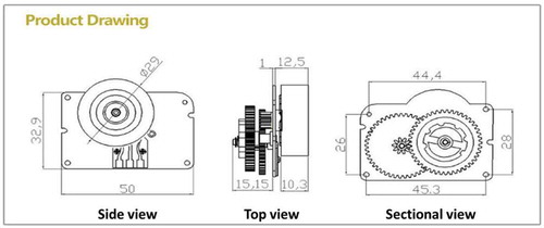
Figure 2. Top view of the fabricated gear pattern and coil spring placement
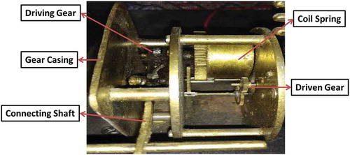
Figure 3. General working principle of mechanical rectification
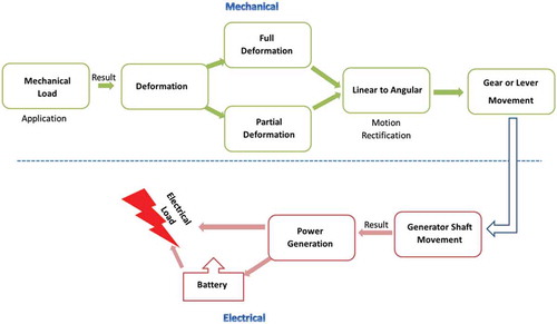
Figure 4. Schematics of implemented energy harvester which depicts complete system arrangement and process flow of the developed system
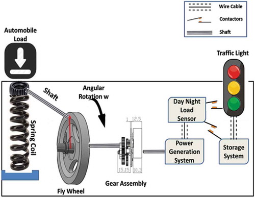
Figure 5. Prototype of energy harvester
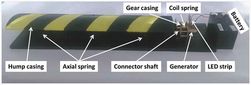
Table 2. Component wise description and their functions
Figure 6. Dimension of model having plate area of 520 mm x 370 mm and hump of 100 mm
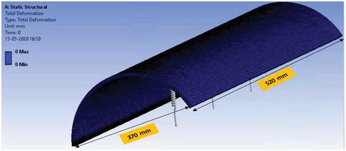
Figure 7. Finite Element Modelling representing deflection contour having uniform distributed loading of 980.67 N
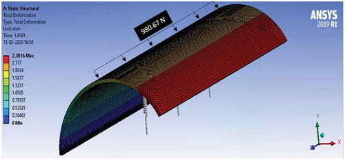
Figure 8. Finite Element Modelling representing deflection contour having uniform distributed loading of 3922.66 N
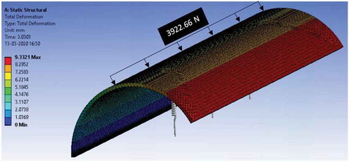
Figure 9. Finite Element Modelling representing deflection contour having uniform distributed loading of 7845.32 N
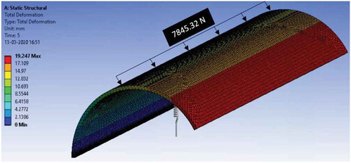
Table 3. Properties of Acrylonitrile Butadiene Styrene (ABS) (MatWeb)
Figure 10. Load vs Deflection curve
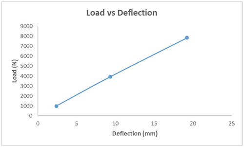
Figure 11. Stress vs Load curve
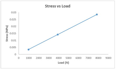
Table 4. Values of various parameters obtained from the laboratory testing due to manual compression
Figure 12. Power Vs time for each sedan crossing over the speed breaker
Figure 13. Synchronous mechanism of alternator at various speeds including synchronous speed