
Figures & data
Figure 1. Global cumulative plastic waste generation and disposal (Geyer, Jambeck, and Law Citation2017).
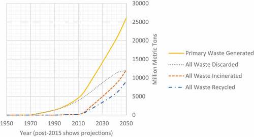
Table 1. Intrinsic properties of common plastics used today (Designer Data Citation2015).
Table 2. Surface energy of common adherents (Jialanella Citation2010).
Figure 2. Shape and dimensions of plastic aggregates sourced.
Table 3. Slump classes (BSI Citation2013).
Table 4. Equivalent fines and sand replacements.
Figure 3. Slump measurement with forms of slump: a) True; b) Shear (adapted after BSI, Citation2019a; BSI Citation2019b and BSI Citation2019c).
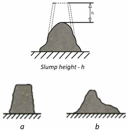
Table 5. 40MPa concrete mix design.
Figure 4. Satisfactory failures of cube specimens (adapted after BSI, Citation2019a; BSI Citation2019b and BS1 Citation2019c).
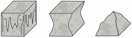
Figure 5. Modified Test Set Up: Push-Out Test, illustrating the adapted push-out test set up used to determine the steel-concrete bond, based on the RILEM: RC6 pull-out test set up (Rilem, Citation1973).
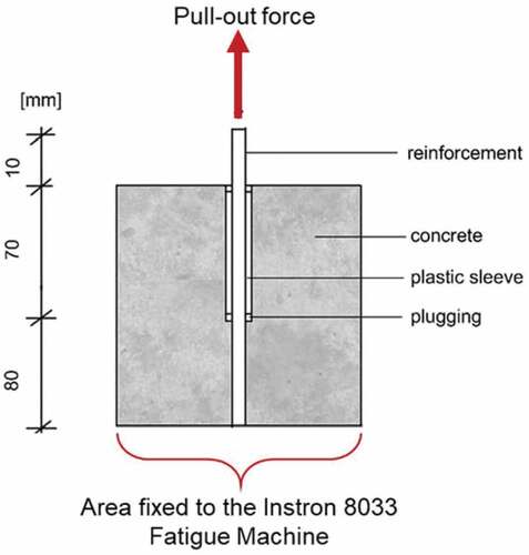
Figure 6. Slump Measurement of Batches (Illustrating the slump height in mm recorded for the 0%, 5%, 10% and 15% batches in this investigation.).
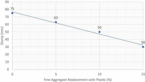
Figure 7. Compressive Strength of All Test Specimens (the recorded compressive strength in MPa of all 12 cube test specimens in this investigation.).
Figure 8. Average Compressive Strength of Each Batch - (the average compressive strength in MPa for the 0%, 5%, 10% and 15% batches in this investigation, calculated using the data in Figure 8.).
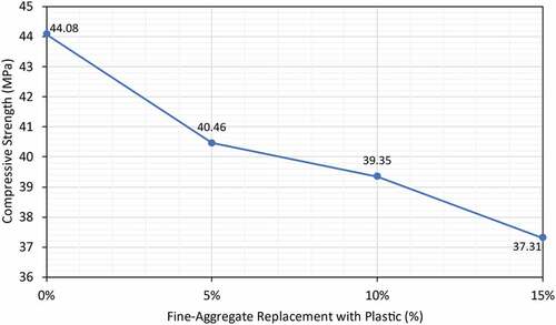
Figure 9. Magnified Image of Plastic Particle Delamination (x10), showing the magnified picture of the delamination between the plastic aggregate and the concrete after failure.
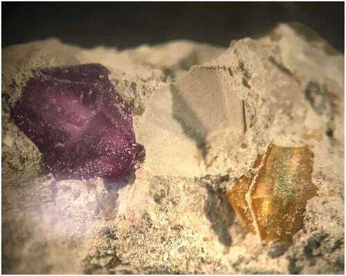
Figure 10. Maximum Push-Out Force of Test Specimens.
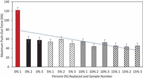
Figure 11. Maximum Bond Strength of Test Specimens.
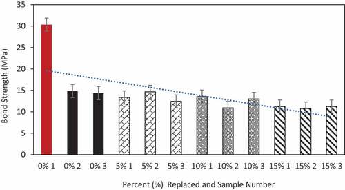
Figure 12. Steel-Concrete Interface After Failure (10% Replacement), illustrating the interface between the steel reinforcement and the concrete specimen for a 10% push-out sample after failure.
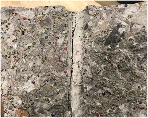
Figure 13. Steel-Concrete Interface After Failure (0% Replacement), illustrating the interface between the steel reinforcement and the concrete specimen for a 0% push-out sample after failure.
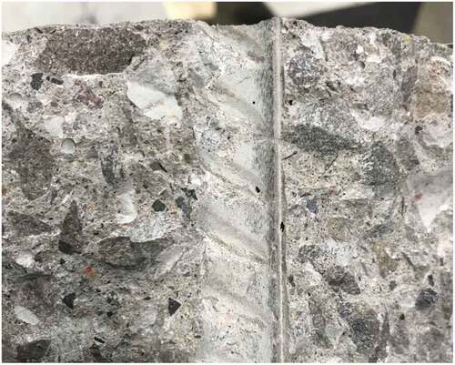
Figure 14. Crushing of Plastic Aggregate at Steel-Concrete Interface. Illustrating the interface between the steel reinforcement and the concrete specimen for a 10% push-out sample after failure, where crushing of a plastic aggregate particle can be observed which contributed to a decrease in the push-out force.
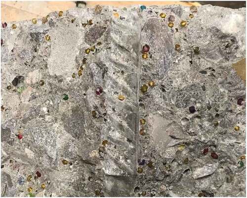
Figure 15. Splitting Failure Displayed by All Reinforced Concrete Pavement Test Specimens, showing the splitting failure mode of all 12 test specimens after failure following the push-out testing.
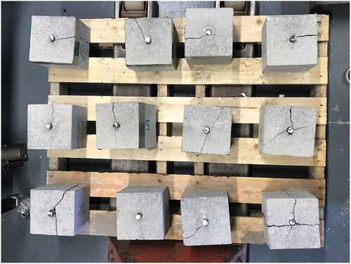
Figure 16. Compression Pavement and Cube Failures for: (a) 0%; (b) 5%; (c) 10%; (d) 15%, illustrating the failure modes of the 3 test specimens for the 0%, 5%, 10% and 15% batches; cracking is observed to be approximately equal for all exposed faces which is considered to be satisfactory.
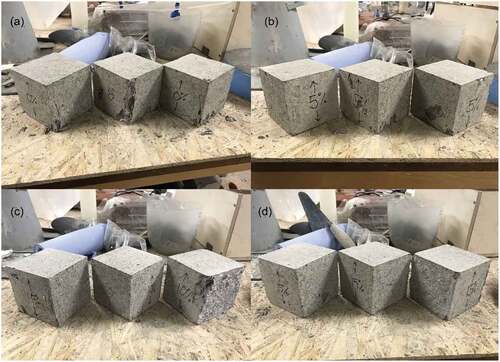
Table 6. Assessment of Slump Requirement.
Table 7. Assessment of Compression Requirement.
Table 8. Assessment of Bond Requirement 1.
Table 9. Assessment of Bond Requirement 2 Based on its Compressive Strength.
Table 10. Assessment of Bond Requirement 3 Based on 40MPa Requirement.
Table 11. Summary of All Requirements.