
Figures & data
Figure 1. Home appliances of the hybrid AC.

Figure 2. AC fan.


Figure 3. (a) BLDC based home appliance – mixie. (b) DC fan.
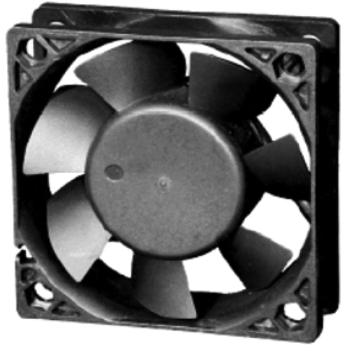
Figure 4. AC and DC grid comparison.
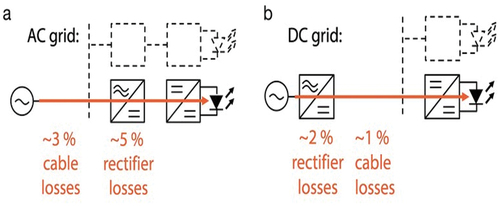
Figure 5. Efficiency comparison.
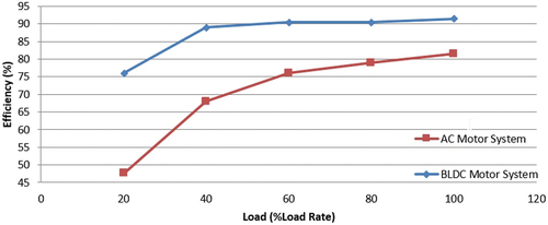
Figure 6. Components of an electronic circuit using AC power (11).
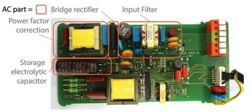
Figure 7. Provision for charging electric vehicle at a DC home.
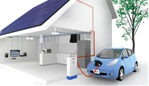
Figure 8. Electrical wiring diagram for AC home.
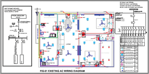
Figure 9. Electrical wiring diagram for proposed DC home.
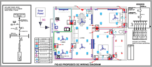
Figure 10. Electrical wiring diagram for existing AEH home.
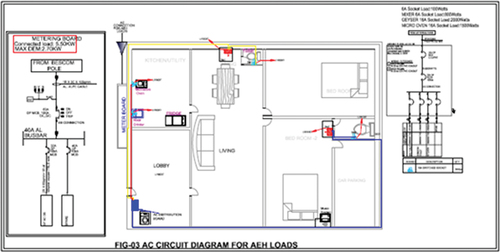
Figure 11. Electrical wiring diagram for hybrid DC-AC home.
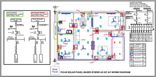
Figure 12. The AC wiring diagram for simulation studies.
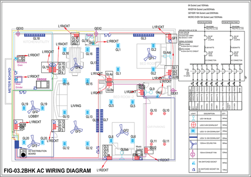
Figure 13. Depicts the AC wiring for AC home which is used for simulation studies.
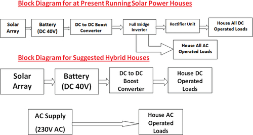
Figure 14. DC simulation report.
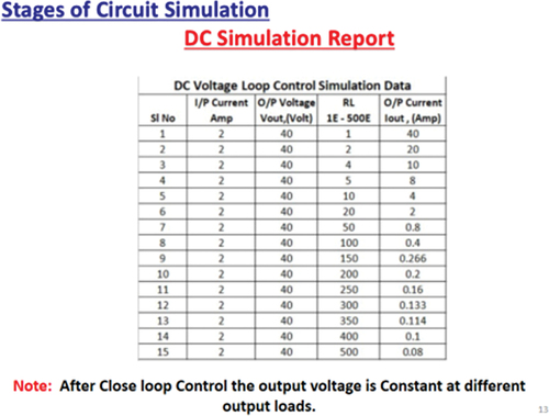
Figure 15. 2.40 volt solar DC voltage simulation data.
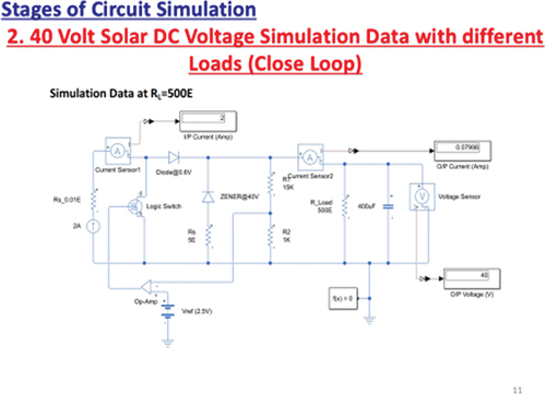
Figure 16. 3.45 volt to 325 volt DC-DC boost converter.
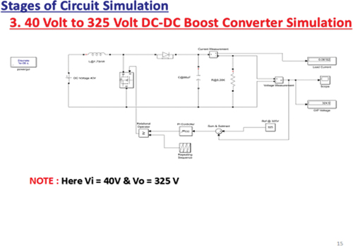
Figure 17. DC simulation report with 40 V input.
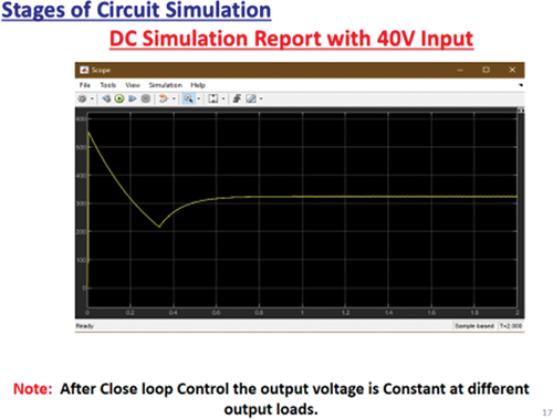
Figure 18. Power demand calculation with different load.
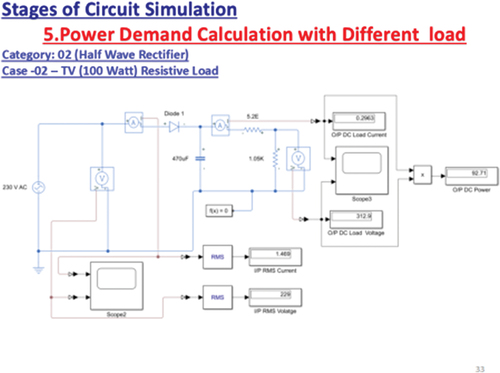
Figure 19. Halfwave rectification.
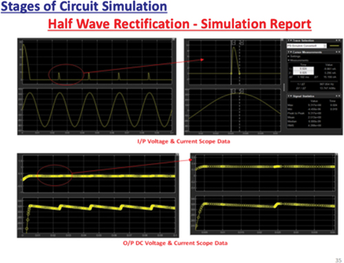
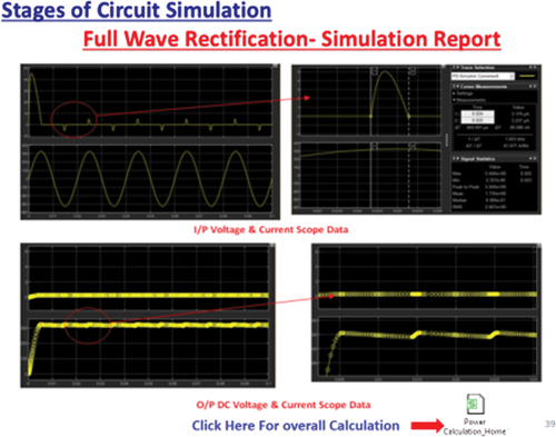
Figure 20. Fullwave rectification.
Data availability statement
The authors have declare no data availability in this manuscript. This paper is my own research work.
