2,221
Views
5
CrossRef citations to date
0
Altmetric
Research articles

Methane emissions from gas engines driving combined heat and power installations

, &
Pages 113-125 | Received 05 Dec 2011, Accepted 22 Mar 2012, Published online: 29 Jun 2012

Figures & data

Figure 1. Schematic figure showing the crevices, piston and cylinder wall.

Figure 1. Schematic figure showing the crevices, piston and cylinder wall.

Figure 2. Overview of the total hydrocarbon emissions of 30 different gas engines as measured by KEMA in 2009, in combination with 8 engines measured in 2007 (Olthuis et al. 2009).
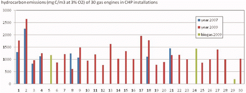
Figure 2. Overview of the total hydrocarbon emissions of 30 different gas engines as measured by KEMA in 2009, in combination with 8 engines measured in 2007 (Olthuis et al. 2009).

Figure 3. Comparison of the HC emissions of the eight engines measured in 2007 as well as in 2009.

Figure 3. Comparison of the HC emissions of the eight engines measured in 2007 as well as in 2009.

Figure 4. Hydrocarbon emission of the gas engines as measured during the second series of measurements (2009) plotted against the measured oxygen concentration (dry) in the exhaust gas. (engines A, etc. are of the same make; engines Ea are of the same type; PC means prechamber).
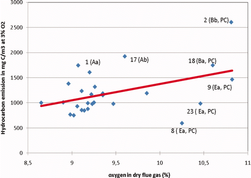
Figure 4. Hydrocarbon emission of the gas engines as measured during the second series of measurements (2009) plotted against the measured oxygen concentration (dry) in the exhaust gas. (engines A, etc. are of the same make; engines Ea are of the same type; PC means prechamber).

Figure 5. HC emissions of five engines measured in 2009 plotted against measured oxygen concentration in the exhaust (blue diamonds) and against net oxygen concentration (red blocks); Engines 8, 9 and 23 are of an identical design.
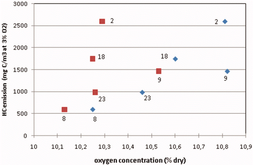
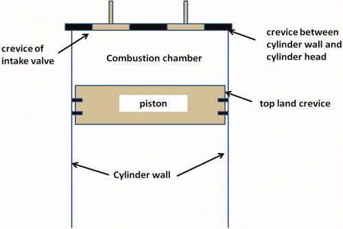
Figure 5. HC emissions of five engines measured in 2009 plotted against measured oxygen concentration in the exhaust (blue diamonds) and against net oxygen concentration (red blocks); Engines 8, 9 and 23 are of an identical design.
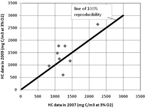
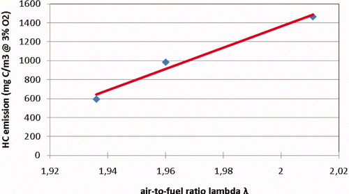
Figure 6. The HC emissions of the prechamber engines 8, 9 and 23 now plotted against the air-to-fuel ratio λ. Note: The unit used to express the HC emission is not influenced by corrections for oxygen not consumed by unburned HC.

Figure 6. The HC emissions of the prechamber engines 8, 9 and 23 now plotted against the air-to-fuel ratio λ. Note: The unit used to express the HC emission is not influenced by corrections for oxygen not consumed by unburned HC.

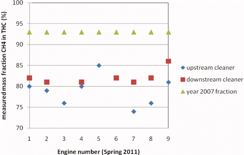
Figure 7. Mass fractions of methane in total hydrocarbons as measured for nine engines with the KEMA system in spring 2011 (fuel is natural gas).

Figure 7. Mass fractions of methane in total hydrocarbons as measured for nine engines with the KEMA system in spring 2011 (fuel is natural gas).

Reprints and Corporate Permissions

Please note: Selecting permissions does not provide access to the full text of the article, please see our help page How do I view content?

To request a reprint or corporate permissions for this article, please click on the relevant link below:

Academic Permissions

Please note: Selecting permissions does not provide access to the full text of the article, please see our help page How do I view content?

Obtain permissions instantly via Rightslink by clicking on the button below:

If you are unable to obtain permissions via Rightslink, please complete and submit this Permissions form. For more information, please visit our Permissions help page.