4,398
Views
69
CrossRef citations to date
0
Altmetric
Original Articles

Migration of nanoparticles from plastic packaging materials containing carbon black into foodstuffs

, &
Pages 1769-1782 | Received 22 Apr 2014, Accepted 04 Aug 2014, Published online: 02 Sep 2014

Figures & data

Table 1. Properties of carbon black grades used in the study.

Table 2. Additives used for mathematical migration modelling.

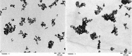
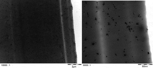
Figure 1. TEM micrographs of carbon black in the dry state: left: Printex® 80, right: Printex® 85.

Figure 1. TEM micrographs of carbon black in the dry state: left: Printex® 80, right: Printex® 85.

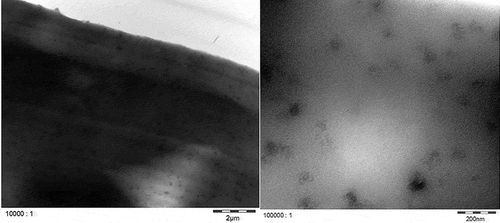
Figure 2. TEM micrographs of 2.5% Printex® 80 in LDPE at two magnifications.

Figure 2. TEM micrographs of 2.5% Printex® 80 in LDPE at two magnifications.

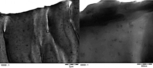
Figure 3. TEM micrographs of 2.5% Printex® 85 in LDPE at two magnifications.

Figure 3. TEM micrographs of 2.5% Printex® 85 in LDPE at two magnifications.

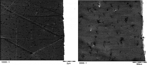
Figure 4. TEM micrographs of 2.5% Printex® 80 in PS at two magnifications.

Figure 4. TEM micrographs of 2.5% Printex® 80 in PS at two magnifications.

Figure 5. TEM micrographs of 2.5% Printex® 85 in PS at two magnifications.

Figure 5. TEM micrographs of 2.5% Printex® 85 in PS at two magnifications.

Figure 6. Signal of the 90° MALLS detector of Printex® 80 (50 µg l–1) overlaid with the solvent blank (black dots) and the calculated radii of gyration per elution time (grey dots).
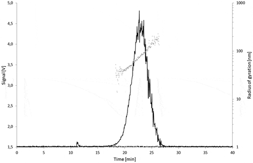
Figure 6. Signal of the 90° MALLS detector of Printex® 80 (50 µg l–1) overlaid with the solvent blank (black dots) and the calculated radii of gyration per elution time (grey dots).
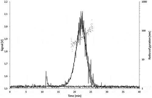
Figure 7. Signal of the 90° MALLS detector of Printex® 85 (50 µg l–1) overlaid with the solvent blank (black dots) and the calculated radii of gyration per elution time (grey dots).

Figure 7. Signal of the 90° MALLS detector of Printex® 85 (50 µg l–1) overlaid with the solvent blank (black dots) and the calculated radii of gyration per elution time (grey dots).

Figure 8. Fractograms of the LDPE migration samples: 5.0% Printex® 80 in LDPE, 5.0% Printex® 85 in LDPE and LDPE blanks of the isooctane (24 h/40°C) and 95% ethanol (10 days/60°C) migration samples.
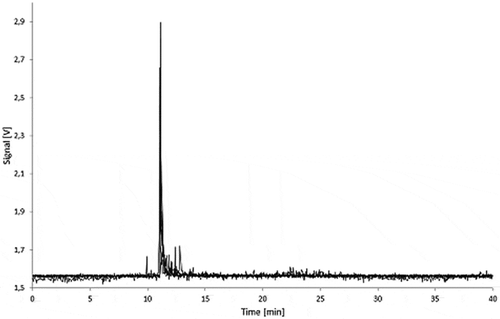
Figure 8. Fractograms of the LDPE migration samples: 5.0% Printex® 80 in LDPE, 5.0% Printex® 85 in LDPE and LDPE blanks of the isooctane (24 h/40°C) and 95% ethanol (10 days/60°C) migration samples.

Figure 9. Fractograms of the LDPE migration samples: 5.0% Printex® 80 in LDPE, 5.0% Printex® 85 in LDPE and LDPE blank of 3% acetic acid (10 days/60°C) migration samples.
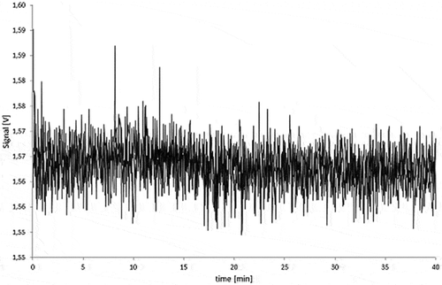
Figure 9. Fractograms of the LDPE migration samples: 5.0% Printex® 80 in LDPE, 5.0% Printex® 85 in LDPE and LDPE blank of 3% acetic acid (10 days/60°C) migration samples.

Figure 10. Fractograms of the PS migration samples: 5.0% Printex® 80 in PS, 5.0% Printex® 85 in PS and PS blanks of the isooctane (24 h/40°C), 95% ethanol (10 days/60°C) migration samples.
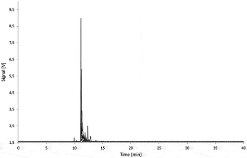
Figure 10. Fractograms of the PS migration samples: 5.0% Printex® 80 in PS, 5.0% Printex® 85 in PS and PS blanks of the isooctane (24 h/40°C), 95% ethanol (10 days/60°C) migration samples.

Figure 11. Fractograms of the PS migration samples: 5.0% Printex® 80 in PS, 5.0% Printex® 85 in PS and PS blank of 3% acetic acid (10 days/60°C) migration samples.
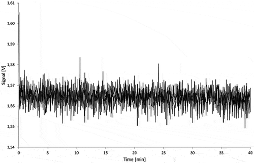
Figure 11. Fractograms of the PS migration samples: 5.0% Printex® 80 in PS, 5.0% Printex® 85 in PS and PS blank of 3% acetic acid (10 days/60°C) migration samples.

Figure 12. 5.0% Printex® 85 in LDPE migration sample (10 days/60°C in 95% ethanol): untreated (black) and spiked with 50 µg l–1 of Printex® 85 (grey).
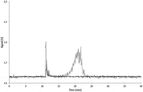
Figure 12. 5.0% Printex® 85 in LDPE migration sample (10 days/60°C in 95% ethanol): untreated (black) and spiked with 50 µg l–1 of Printex® 85 (grey).

Figure 13. 5.0% Printex® 80 in PS migration sample (24 h/40°C in isooctane): untreated (black) and spiked to 25 µg l–1 with Printex® 80 (grey).
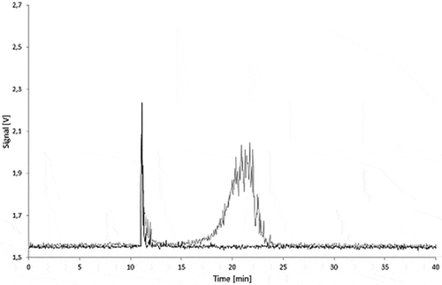
Figure 13. 5.0% Printex® 80 in PS migration sample (24 h/40°C in isooctane): untreated (black) and spiked to 25 µg l–1 with Printex® 80 (grey).

Figure 14. Sequential dilution of Printex® 80: blank, 10, 25, 50, 100 and 250 µg l–1; signal of the 90° MALLS detector.
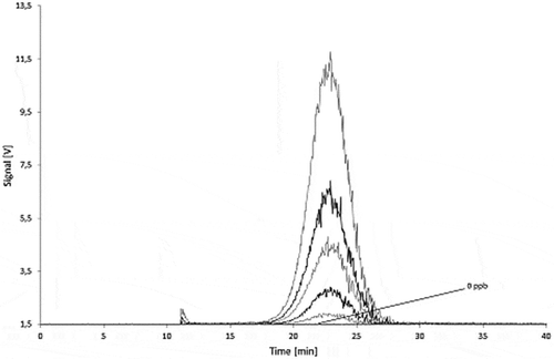
Figure 14. Sequential dilution of Printex® 80: blank, 10, 25, 50, 100 and 250 µg l–1; signal of the 90° MALLS detector.

Figure 15. Sequential dilution of Printex® 85: blank, 10, 25, 50, 100 and 250 µg l–1 signal of the 90° MALLS detector.
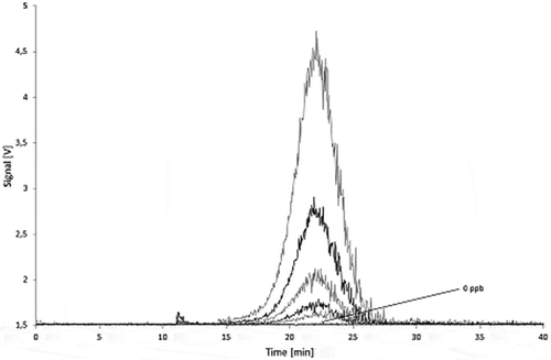
Figure 15. Sequential dilution of Printex® 85: blank, 10, 25, 50, 100 and 250 µg l–1 signal of the 90° MALLS detector.

Figure 16. Calibration curve for Printex® 80: total MALLS output versus concentration of standard (1000 µl injections) with relative standard deviations.
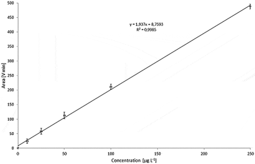
Figure 16. Calibration curve for Printex® 80: total MALLS output versus concentration of standard (1000 µl injections) with relative standard deviations.
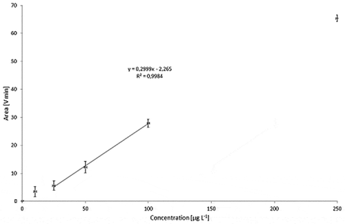
Figure 17. Calibration curve for Printex® 85: Total MALLS output versus concentration of standard (1000 µl injections) with relative standard deviations.

Figure 17. Calibration curve for Printex® 85: Total MALLS output versus concentration of standard (1000 µl injections) with relative standard deviations.

Figure 18. Stability of a Printex® 80 dispersion in 95% ethanol: signal of the 90° MALLS detector of a freshly prepared dispersion (black) and of a dispersion stored for 10 days at 60°C (grey).
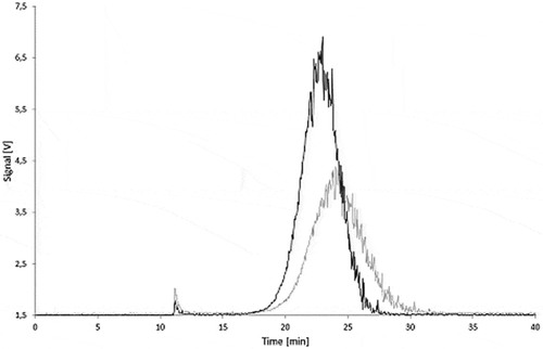
Figure 18. Stability of a Printex® 80 dispersion in 95% ethanol: signal of the 90° MALLS detector of a freshly prepared dispersion (black) and of a dispersion stored for 10 days at 60°C (grey).
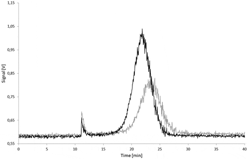
Figure 19. Stability of a Printex® 85 dispersion in 95% ethanol: signal of the 90° MALLS detector of a freshly prepared dispersion (black) and of a dispersion stored for 10 days at 60°C (grey).

Figure 19. Stability of a Printex® 85 dispersion in 95% ethanol: signal of the 90° MALLS detector of a freshly prepared dispersion (black) and of a dispersion stored for 10 days at 60°C (grey).

Table 3. Stability of carbon black in 95% ethanol at migration conditions (1000 µl injections of 100 µg l−1 dispersions).

Table 4. Stability of carbon black in isooctane and 3% acetic acid at migration conditions (1000 µl injections of 100 µg l−1 dispersions).

Table 5. Migration modelling of three additives in relation to their molecular size (plaques 3 mm, 5% additive concentration, 10 days/40°C, K = 1, surface to volume ratio 6 dm2 kg−1).

Table 6. Comparison of diffusion coefficients at 25°C obtained according to Simon et al. (Citation2008) with that according to the modelling guideline (Simoneau Citation2010).