1,255
Views
6
CrossRef citations to date
0
Altmetric
Articles

Management of BWRO systems using long-term monitoring of feed water quality to avoid future membrane process failure

, , &
Pages 16209-16219 | Received 18 Jun 2015, Accepted 25 Jul 2015, Published online: 12 Aug 2015

Figures & data

Fig. 1. Map showing the location of the Bonita Springs Utilities BWRO facility and the wellfield and wells that are used to obtain feed water.
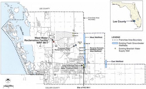
Fig. 1. Map showing the location of the Bonita Springs Utilities BWRO facility and the wellfield and wells that are used to obtain feed water.

Table 1 Well numbers with construction details

Fig. 2. Hydrogeologic cross-section of the Bonita Springs Utilities wellfield.

Fig. 2. Hydrogeologic cross-section of the Bonita Springs Utilities wellfield.

Table 2 Dissolved chloride and TDS concentrations in the water from the production wells at the beginning of production, at the end of 2014, and projections to 40 years

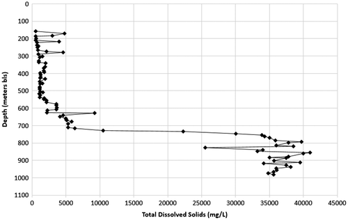
Fig. 3. Water quality variation with depth at the injection well test site.

Fig. 3. Water quality variation with depth at the injection well test site.

Fig. 4. Diagram showing the variation in pumpage and associated dissolved chloride and TDS concentrations in time for the ten-year operating period, 2014–2014 (a) well 25 (b) well 26 (c) well 27 (d) well 28 (e) well 29 (f) well 30 (g) well 31 (h) well 32.
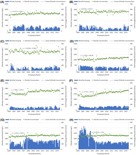
Fig. 4. Diagram showing the variation in pumpage and associated dissolved chloride and TDS concentrations in time for the ten-year operating period, 2014–2014 (a) well 25 (b) well 26 (c) well 27 (d) well 28 (e) well 29 (f) well 30 (g) well 31 (h) well 32.

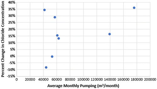
Fig. 5. Plot of average pumping rate per month vs. percentage change in dissolved chloride change.

Fig. 5. Plot of average pumping rate per month vs. percentage change in dissolved chloride change.

Fig. 6. Conceptual model used to assess projected future water quality changes within the production aquifer.
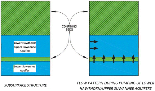
Fig. 6. Conceptual model used to assess projected future water quality changes within the production aquifer.
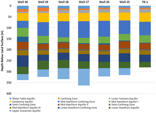
Table 3 Bonita Springs BWRO plant specifications and characteristics

Fig. 7. Treatment process diagram for the Bonita Springs Utilities BWRO treatment plant.

Fig. 7. Treatment process diagram for the Bonita Springs Utilities BWRO treatment plant.