Figures & data
Table 1 Experimental conditions used for biofilm growth for each non-destructive biofilm characterization technique
Fig. 1. OCT 2-D image of a grown biofilm on a membrane surface without feed spacer in an area of a 3.83 mm × 0.85 mm. The membrane is shown at the bottom of the figure. The biofilm had a heterogeneous structure containing voids.

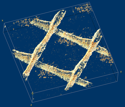
Fig. 2. 3-D reconstruction of a biofilm grown on the surface of a membrane and feed spacer in a flow cell; the image was obtained after processing OCT 3-D scans in an area of 6 mm × 6 mm × 1.08 mm. Spacer filaments contained most of the biomass detected.

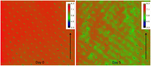
Fig. 3. Spatial distribution of oxygen concentration (mg L−1) at the inlet side of the MFS on day 0 and after 5 days of biofilm development. The arrow indicates the water flow direction. Scale bar represents oxygen concentration (mg L−1). The imaged area is 4.0 mm × 3.5 cm. Biofilm accumulation started on the feed spacer.

Fig. 4. The second moment (σ2) of the fouling RO membrane module acquired using EF NMR compared to the feed channel pressure drop as a function of fouling time. The equation to calculate the second moment (σ2) through the signal intensity (S) and magnitude (|S(k)/Smax|) in k-space is shown (adapted from Fridjonsson et al. [Citation32]). NMR detection of biofouling is at an earlier stage than the pressure drop increase.
![Fig. 4. The second moment (σ2) of the fouling RO membrane module acquired using EF NMR compared to the feed channel pressure drop as a function of fouling time. The equation to calculate the second moment (σ2) through the signal intensity (S) and magnitude (|S(k)/Smax|) in k-space is shown (adapted from Fridjonsson et al. [Citation32]). NMR detection of biofouling is at an earlier stage than the pressure drop increase.](/cms/asset/bea34ada-6c78-4651-adbf-721419d1ce65/tdwt_a_1180483_f0004_b.gif)
