
Figures & data
Figure 1. SGUF: geometry description and employed coordinates across the thickness.
Table 1. T1: Material data for the transversely isotropic PZT-5 material polarized along the direction. Superscripts
and
specify that the coefficients are given at constant electric field and at constant strain, respectively. Plate length
[m], thickness
[m].
Figure 2. T1: Convergence analysis for first and sixth eigenfrequencies of the CC and CF plate.
Table 2. T1: Circular eigenfrequencies [] for the hinged-hinged (SS) plate.
Table 3. T1: Circular eigenfrequencies [] for the clamped-clamped (CC) plate.
Table 4. T1: Circular eigenfrequencies [] for the clamped-free (CF) plate.
Table 5. T1: Circular eigenfrequencies [] for the clamped-hinged (CS) plate.
Figure 3. T1: Ratio between the eigenfrequencies of the piezoelectric plate and those of the equivalent elastic plate for different mechanical boundary conditions and electric circuits.
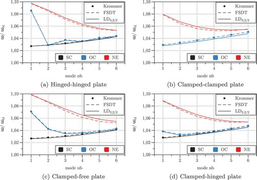
Figure 4. T1: Modal Electro-Mechanical Coupling Coefficient for different mechanical boundary conditions with and without equipotential electrode conditions.
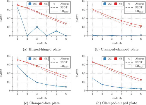
Table 6. T2: Material data for PZT-5A (transverse isotropy in plane) and for GrEp (transverse isotropy in
plane). Superscripts
and
specify that the coefficients are given at constant electric field and at constant strain, respectively.
Table 7. T2: Comparison between local non-dimensional response obtained with the quasi-3D model ED/LD
with
and the analytical 3D solution.
Figure 5. T2-Sensor configuration: influence of the boundary conditions on the mechanical response of the PZT/GrEp laminate subjected to an external pressure load.
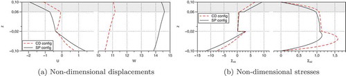
Figure 6. T2-Actuator configuration: influence of the boundary conditions on the mechanical response of the PZT/GrEp laminate under the action of an electric potential difference in the PZT ply.
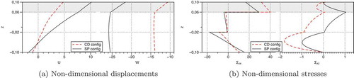
Table 8. T3: Material data for the face and core materials.
Figure 7. T3: (a) double sandwich plate with bonded piezoelectric plies; (b) subdivision in sublaminates; (c) subdivision in
sublaminates.
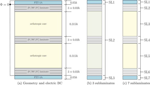
Table 9. T3: assessment of models with one, three and seven sublaminates for a thick plate .
Table 10. T3: assessment of models with with one, three and seven sublaminates for a moderately thin plate .