
Figures & data
Figure 1. Elements of an external electrical circuit: (a) – resistance (), (b) – capacitance (
), (c) inductance (
).
Figure 2. Calculation schemes of structures with a piezoelectric element: (a) plate; (b) shell.
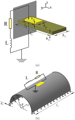
Figure 3. Surfaces of the real part of the first complex eigenfrequency (blue) and the frequency of the electrical circuit oscillations (red) for the plate (a) and shell (c) and the projections of their coincidence lines for the plate (b) and shell (d).
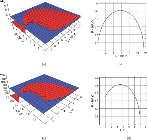
Figure 4. Surfaces of dependence of the imaginary parts of the first complex eigenfrequency of the structure (colored) and the integrated complex frequency of oscillatory circuit (gray) on the and
parameters of the external circuit for the plate (a) and the shell (b).
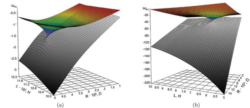
Figure 5. Surfaces of dependence of the imaginary part of the first complex eigenfrequency of the structure on the and
parameters of the external circuit for the plate (a) and the shell (b).
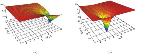
Table 1. The results of definition of optimal parameters of shunt circuit and
for two vibration modes of the plate and the shell on the basis of formulas (20) and condition (17).