Figures & data
Figure 1. Schematics of (a) a bi-material strip with three design patterns: (b) standard design; (c) E-shape design; (d) S-shape design.
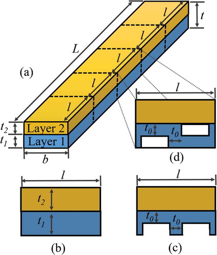
Figure 2. Curvature variation with respect to modulus ratio and thickness ratio of the bi-material strip.
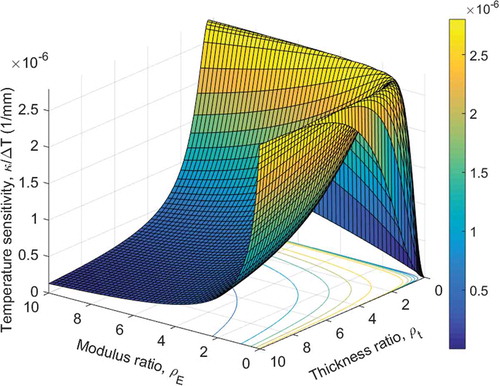
Figure 3. Thermal sensitivity variation with respect to different design parameters: (a) thickness; (b) CTE difference; (c) thickness ratio; and (d) modulus ratio.
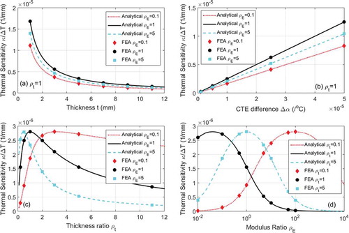
Figure 4. Normalized deflection variation of three design patterns with respect to ρt and volume fraction Vf at ρE = 0.1.
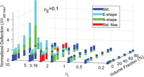
Figure 5. Normalized deflection variation of three design patterns with respect to ρt and volume fraction Vf at ρE = 1.
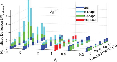
Figure 6. Normalized deflection variation of three design patterns with respect to ρt and volume fraction Vf at ρE = 10.
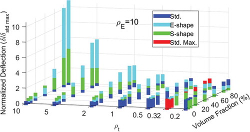
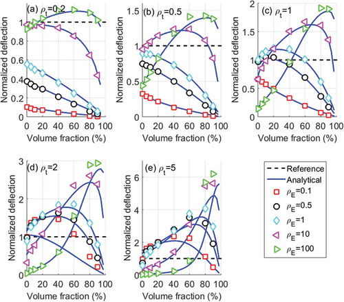
Figure 7. Normalized deflection variation comparison between analytical prediction and FEA simulation of E-shape design, with respect to volume fraction, thickness ratio and modulus ratio.