
Figures & data
Figure 1. Hierarchical structure of bone spanning from macro to nanoscale. The shaft of long cortical bone is primarily made of cylindrical features called osteon. Osteon includes several concentric rings, each called a lamella. Inside a given lamella, ultrastructure of bone consists of alternating array of Mineralized Collagen Fibrils (MCF) and Extrafibrillar Matrix (EFM). MCF is made by a staggered arrangement of hydroxyapatite (HA) platelets mostly residing within the soft collagen matrix. EFM is comprised of HA crystals bonded by thin layers of Non-Collagenous Proteins (NCPs).
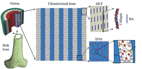
Figure 2. The proposed material model is a hybrid composite inspired by ultrastructure of bone. It consists of an alternating parallel array of two basic subunits A and B connected together by a thin layer of adhesive phase. The subunits A and B represent the mineralized collagen fibril and extrafibrillar matrix of bone ultrastructure, respectively.
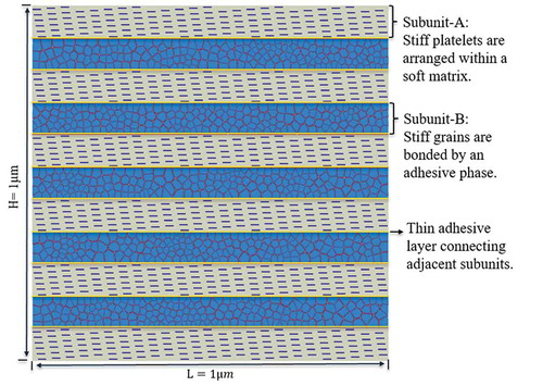
Figure 3. (a) The process of Centroidal Voronoi tessellation to create the geometry of randomly shaped and distributed grains inside subunit-B; (b) The process of inserting cohesive elements representing adhesive phase in between stiff grains.
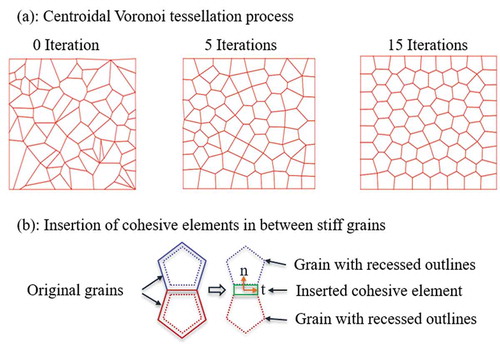
Figure 4. A zoom-in view of mesh.
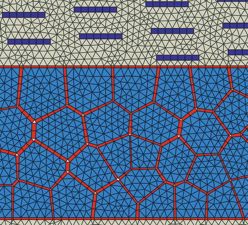
Figure 5. A typical bilinear traction-separation law.
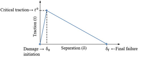
Table 1. Material parameters used for modeling soft and hard phases.
Table 2. Material parameters used for modeling the adhesive phase.
Figure 6. Boundary conditions for modeling the bioinspired composite.
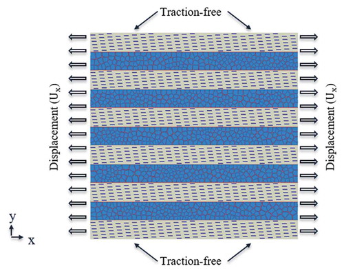
Figure 7. The conventional composite model. Cohesive elements were embedded in fibers at vertical direction to model the fiber failure.
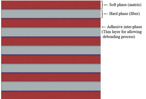
Figure 8. Stress contour at different applied strains: (a) at pre-yield stage of deformation, subunit-B was major load-bearing subunit, experiencing high tensile stress; (b-c) in post-yield stage of deformation, damage started and evolved in adhesive phase, creating multiple cracks within subunit-B that gave rise to energy dissipation; (d) Stress in soft phase reached to its critical strength and crack propagated into soft matrix to form a final failure crack.
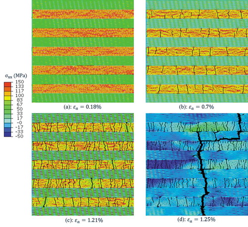
Figure 9. Stress-strain relation of the bulk composite and its basic subunits. At pre-yield stage of deformation, subunit-B was the primary load-bearing subunit. The composite showed an appreciable amount of post-yield deformation up to reaching to its ultimate strength. During the post yield deformation, stress kept relaxing in subunit-B, due to damage and cracking of the thin adhesive layers bonding the stiff grains. However, load was being gradually transferred to subunit-A such that stress kept increasing in subunit-A.
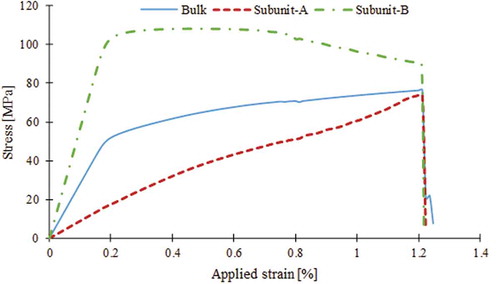
Figure 10. Stress distribution and damage process of the conventional composite model subjected to tensile loading along the fiber direction (x-direction).
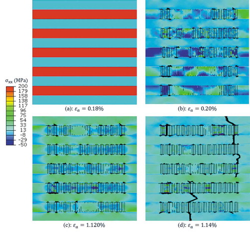
Figure 11. Stress-strain relation for the bioinspired and conventional composite model.
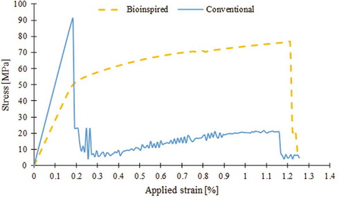
Table 3. The mechanical properties of bioinspired and conventional composite.