Figures & data
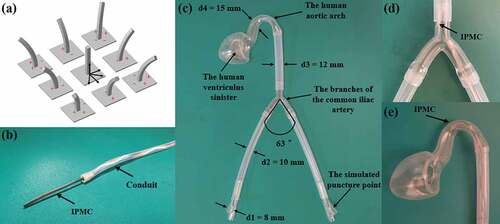
Figure 1. The fabrication of square rod-shaped Nafion membrane.
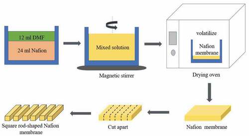
Figure 2. The fabrication and segmentation of IPMC electrodes.
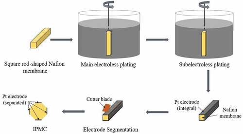
Figure 3. The images of Nafion and IPMC. (a) the square rod-shaped Nafion matrix; (b) the square rod-shaped IPMC.
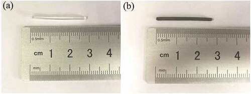
Figure 4. The schematic diagram of the test platform.
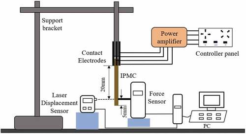
Figure 5. The diagram of angle derivation.
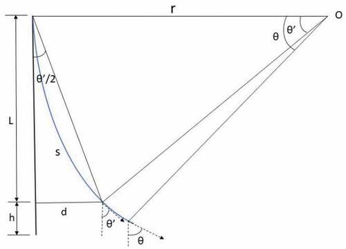
Figure 6. The images of SEM. (a) surface electrode layer; (b) cross-sectional electrode layer.
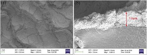
Figure 7. The motion sketch of the square rod-shaped IPMC.
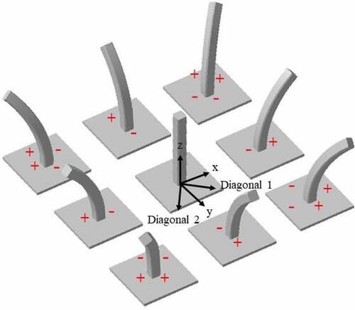
Figure 8. The angle curves of the square rod-shaped IPMC under 2 ~ 8 V DC. (a) x-direction; (b) y-direction; (c) diagonal 1-direction; (d) diagonal 2-direction.
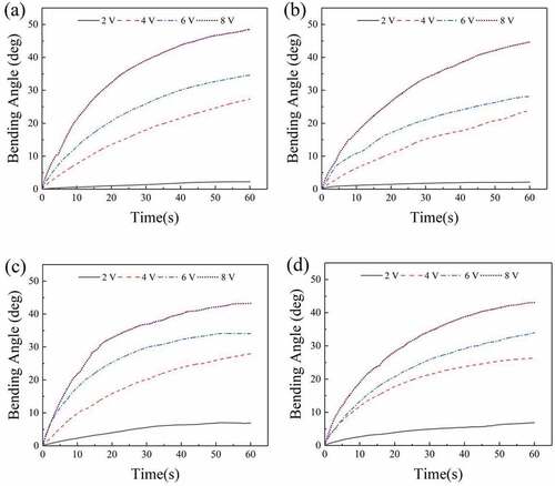
Figure 9. The blocking force curves of the square rod-shaped IPMC under 2 ~ 8 V DC. (a) Diagonal 1-direction; (b) Diagonal 2-direction.
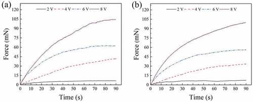
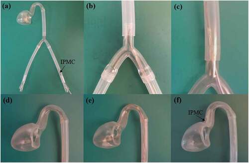
Figure 10. The interventional catheter. (a) the front end of the catheter; (b) the side view of the catheter.
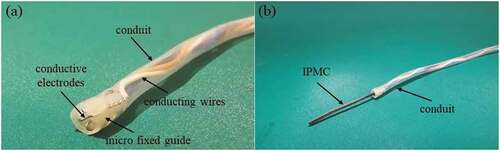
Figure 11. The human aortic vascular model.
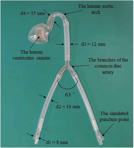
Figure 12. The simulation experiment of interventional surgical operation. (a) the intervention at puncture point; (b) the guidance at branch of iliac aorta. (c) the IPMC restored to flat state; (d) the guidance at aortic arch; (e) angle adjustment and forward propulsion; (f) arrived the left ventricle.