Figures & data

Figure 1. A schematic of a moisture-based actuation in our cellulose membranes
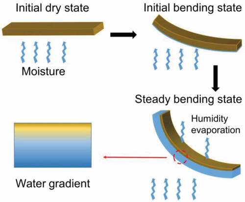
Figure 2. (a) A schematic diagram of the device for testing humidity responsivity. θ denotes the deflection angle of the membrane upon exposure to the moisture gradient (shown in blue). (b) A scanning electron microscope image of the cross-section of a cellulose membrane. (c) A scanning electron microscope image of a laterally compressed membrane
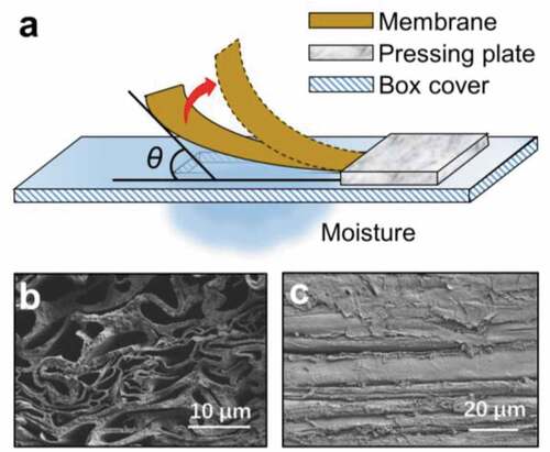
Figure 3. (a) Fourier transform infrared spectroscopy analysis of the cellulose membrane. Inset: measured contact angle (CA = 43.66°) of the membrane. (b) Stress-strain curve of a dry cellulose membrane
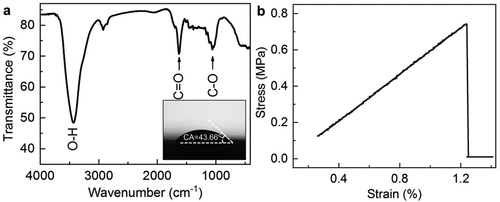
Figure 4. (a) Evolution of moisture-induced curvature (ρ) of a bent membrane with time (t) under different relative humidity differences (ΔRH). (b) A relationship of the ρ versus ΔRH. The insets show the bent membranes at ΔRH = 9% and 44%, respectively
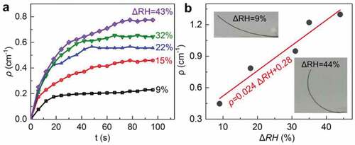
Figure 5. Effect of membrane size on the deflection angle (θ) and curvature (ρ). (a) The θ versus width (black) at a given length of 1.5 cm; the red data show results of θ versus the length, at a given width of 0.3 cm. (b) Profiles of bent membranes with different lengths, under a given ΔRH = 44%. (c) The relation between curvature (ρ) and the thickness (H) of the membranes. The length and width of the membrane are 1.6 and 0.8 cm, respectively. The relative humidity difference between two opposite surfaces of the membrane is around 50%
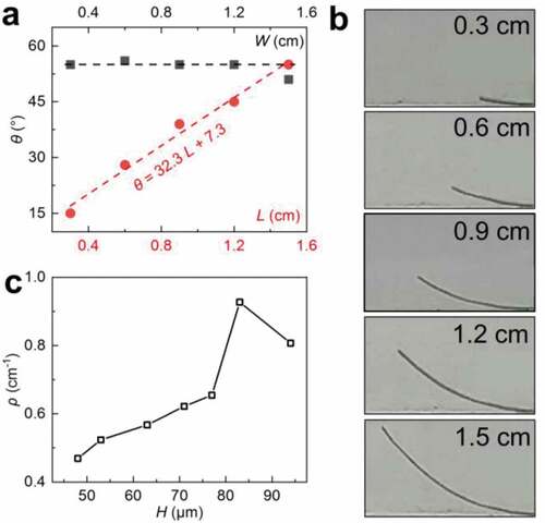
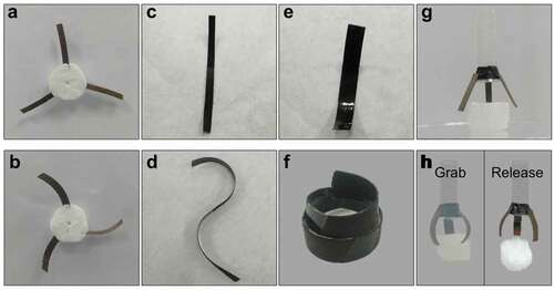
Figure 6. Pre-determined deformations and application of the actuators. When the actuators are transferred from the ambient environment (a, c, e, g) to a high humidity environment with a relative humidity of 99% (b, d, f, h), their shapes will change according to the designs. (a, b) Curve. One surface of the actuator is completely sealed by a transparent tape. (c, d) S-like curve. The upper half is sealed on the left-hand side while the lower half is sealed on the right. (e, f) Curl. One surface is completely sealed while the other is partially sealed. (g, h) A three-finger gripper, which can grab, hold and release a 0.62 g foam 40 times the weight of the three fingers