
Figures & data
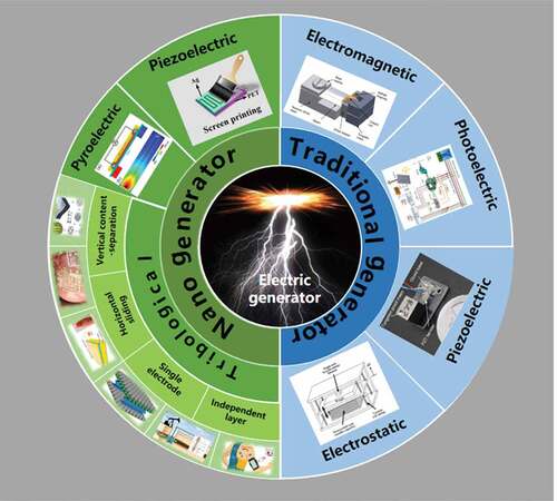
Figure 1. Traditional types of electric power generation (right) and new types of electric power generation by nanogenerators (left) [Citation1–4,Citation6–12,Citation15]
![Figure 1. Traditional types of electric power generation (right) and new types of electric power generation by nanogenerators (left) [Citation1–4,Citation6–12,Citation15]](/cms/asset/abcc14a1-bc01-4317-b5d5-859eea61b86e/tsnm_a_1973143_f0001_c.jpg)
Figure 2. Working mechanism of the first flexible triboelectric nanogenerator [Citation28]
![Figure 2. Working mechanism of the first flexible triboelectric nanogenerator [Citation28]](/cms/asset/42e6827c-3c94-480e-8cb5-5a8d71b2924d/tsnm_a_1973143_f0002_c.jpg)
Table 1. Application of triboelectric nanogenerators in in vitro detection and wearable devices
Figure 3. First demonstrated flexible self-powered blood oxygen detect system based on triboelectric nanogenerator [Citation7]
![Figure 3. First demonstrated flexible self-powered blood oxygen detect system based on triboelectric nanogenerator [Citation7]](/cms/asset/56857643-6388-4f2a-8d26-7f1dc522f3a4/tsnm_a_1973143_f0003_c.jpg)
Figure 4. TENG used in smart shoes. (a) A completely flexible array of nanogenerators used to collect energy generated during walking [Citation40]. (b) A real-time foot pressure monitoring insole based on the nanogenerator [Citation41].(c) A laboratory model of self-powered intelligent footwear using a TENG/EMG hybrid strategy [Citation42]
![Figure 4. TENG used in smart shoes. (a) A completely flexible array of nanogenerators used to collect energy generated during walking [Citation40]. (b) A real-time foot pressure monitoring insole based on the nanogenerator [Citation41].(c) A laboratory model of self-powered intelligent footwear using a TENG/EMG hybrid strategy [Citation42]](/cms/asset/38efce1d-a8dc-473a-a510-944114bd6c8b/tsnm_a_1973143_f0004_c.jpg)
Figure 5. A self-powered sweat monitoring device. (a) Schematic illustration of the FTENG-powered wearable sweat sensor system. (b–c) Optical images of the wearable system. The scale bars are 4 cm. (d) The structural diagram of FTENG. (e) Schematic diagram of the sweat sensor patch contacted with the flexible circuitry. (f) Working logic diagram of the system [Citation8]
![Figure 5. A self-powered sweat monitoring device. (a) Schematic illustration of the FTENG-powered wearable sweat sensor system. (b–c) Optical images of the wearable system. The scale bars are 4 cm. (d) The structural diagram of FTENG. (e) Schematic diagram of the sweat sensor patch contacted with the flexible circuitry. (f) Working logic diagram of the system [Citation8]](/cms/asset/6e527c7b-5a68-4f71-b409-f7f06fbeeb8e/tsnm_a_1973143_f0005_c.jpg)
Figure 6. Detection devices for tensile vibration signal based on TENG. (a) A self-powered stretchable transparent nanogenerator to monitor the signals of eye movements or sound vibrations [Citation44]. (b) A multi-function stretchable, yarn-embedded electronic skin[Citation45]
![Figure 6. Detection devices for tensile vibration signal based on TENG. (a) A self-powered stretchable transparent nanogenerator to monitor the signals of eye movements or sound vibrations [Citation44]. (b) A multi-function stretchable, yarn-embedded electronic skin[Citation45]](/cms/asset/821a9683-27e2-4363-87f6-842f45bb9918/tsnm_a_1973143_f0006_c.jpg)
Figure 7. Applications of TENG in air purification and respiratory surveillance. (a) A self-powered respiration monitoring system based on Ag nanowires [Citation9]. (b) A TENG used for respiratory detection which collected energy from airflow disturbances [Citation49]
![Figure 7. Applications of TENG in air purification and respiratory surveillance. (a) A self-powered respiration monitoring system based on Ag nanowires [Citation9]. (b) A TENG used for respiratory detection which collected energy from airflow disturbances [Citation49]](/cms/asset/f8aaa1e0-33a8-4403-afc8-c48f017714c3/tsnm_a_1973143_f0007_c.jpg)
Figure 8. TENG-powered implantable devices in the body. TENG used to detect changes in lung (a), bladder (b, c), stomach (d), and joint surface [Citation54,Citation55,Citation56,Citation10]
![Figure 8. TENG-powered implantable devices in the body. TENG used to detect changes in lung (a), bladder (b, c), stomach (d), and joint surface [Citation54,Citation55,Citation56,Citation10]](/cms/asset/1f3d60d8-c464-4788-b118-12e0431643e8/tsnm_a_1973143_f0008_c.jpg)
Figure 9. TENGs used for environmental monitoring. (a) A Hg2+ monitoring sensor [Citation59,Citation60]. (b) A sensor monitoring the moving speed of bubbles [Citation11]. (c) A triboelectric nanogenerator and electromagnetic generator mixed device to detect wind speed [Citation61]. (d) Flame-retardant textile-based triboelectric nanogenerators for fire protection applications [Citation12]
![Figure 9. TENGs used for environmental monitoring. (a) A Hg2+ monitoring sensor [Citation59,Citation60]. (b) A sensor monitoring the moving speed of bubbles [Citation11]. (c) A triboelectric nanogenerator and electromagnetic generator mixed device to detect wind speed [Citation61]. (d) Flame-retardant textile-based triboelectric nanogenerators for fire protection applications [Citation12]](/cms/asset/e7622d67-d5e1-486a-a650-93a47e8abfb2/tsnm_a_1973143_f0009_c.jpg)
Figure 10. TENGs used for the collection of Marine energy. (a) A smooth rubber ball connected to several rubber balls to increase output efficiency[Citation65]. (b) A sealed ball with spring multilayer structure to enhance the output performance by amplifying the wave vibration [Citation64]. (c) A spring-assisted TENG with a silicone rubber segmented electrode structure [Citation65]. (d) TENG inspired from bionic jellyfish. (e) A high-sensitivity wave sensor based on a liquid-solid interface triboelectric nanogenerator. (f) A triboelectric nanogenerator for collecting underwater ultrasonic energy [Citation67–69]
![Figure 10. TENGs used for the collection of Marine energy. (a) A smooth rubber ball connected to several rubber balls to increase output efficiency[Citation65]. (b) A sealed ball with spring multilayer structure to enhance the output performance by amplifying the wave vibration [Citation64]. (c) A spring-assisted TENG with a silicone rubber segmented electrode structure [Citation65]. (d) TENG inspired from bionic jellyfish. (e) A high-sensitivity wave sensor based on a liquid-solid interface triboelectric nanogenerator. (f) A triboelectric nanogenerator for collecting underwater ultrasonic energy [Citation67–69]](/cms/asset/9655b32c-87d5-4823-a664-4928812f0518/tsnm_a_1973143_f0010_c.jpg)
Figure 11. Environmentally friendly triboelectric nanogenerator. (a) Natural biopolymer-based triboelectric nanogenerators [Citation70]. (b) TENG using leaves as rubbing materials to capture wind energy [Citation71]
![Figure 11. Environmentally friendly triboelectric nanogenerator. (a) Natural biopolymer-based triboelectric nanogenerators [Citation70]. (b) TENG using leaves as rubbing materials to capture wind energy [Citation71]](/cms/asset/26703440-7c8b-47bf-993a-dc4a3301a10d/tsnm_a_1973143_f0011_c.jpg)