
Figures & data
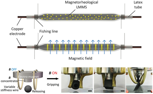
Figure 1. Variable stiffness wires based on LMMS. (a) Schematics showing the process for preparing the LMMS. (b) Schematic illustrating the stiffness changing mechanism of variable stiffness wire. (c) Stretching of variable stiffness wire in the energized state (in a strain of 400%). Scale bar, 1 cm. (d) Compressing of variable stiffness wires under non-magnetic and magnetic environment. Scale bar, 1 mm.
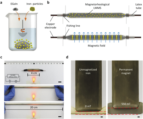
Figure 2. Characterization of electrical conductivity and variable stiffness properties of wires. (a) Changes in the resistance with respect to stretch length. (b) Changes of the resistance with respect to magnetic flux density at different ratios of LM to Fe particles. (c) Changes of the stiffness with respect to magnetic flux density at different ratios of LM to Fe particles. Inset: setup of radial stiffness change measurement. (d) Changes of the stretchability of wires at different magnetic flux densities (applied weights of 50 g). Inset: setup of axial stiffness change measurement.
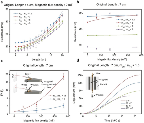
Figure 3. Examples of applications of the various stiffness wires. (a) Photographs of the shape maintaining ability of the LMMS wire under a magnetic field; (b) Photographs of on/off control of the circuit based on the variable stiffness wire; (c) Changes in the circuit current when pressure is applied on the wire. (d) Photographs of soft gripper based on various stiffness wires. Scale bars, 1 cm.
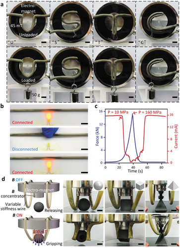
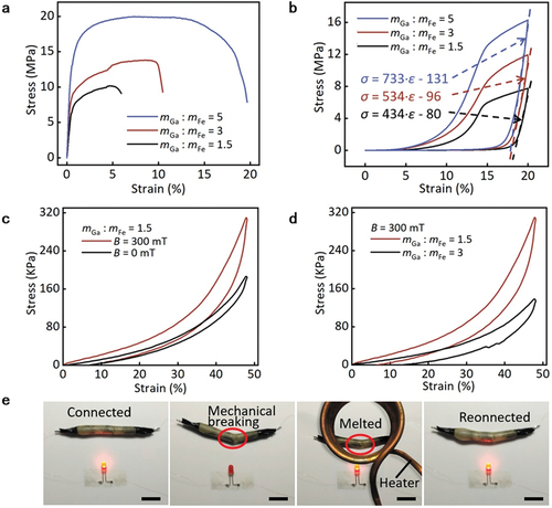
Figure 4. Characterization of mechanical properties of Ga-based LMMS wires. Stress–strain curves of the solid-state Ga-based LMMS wires with three different mass ratios under (a) tension and (b) compression. (c) Stress–strain curves of the liquid-state LMMS wires within magnetic fields of 0 mT and 300 mT under compression. The mass ratio is 1.5. (d) Stress–strain curves of the liquid-state LMMS wires with mass ratios of 1.5 and 3 under compression. The magnetic field is 300 mT. (e) Photographs showing disconnection and self-healing of the circuit based on the Ga-based LMMS wire. Scale bar, 1 cm.
Data availability statement
The data presented in this study are available on request from the corresponding author.