Figures & data
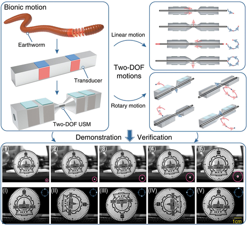
Figure 1. The locomotion mechanism of the earthworm and bonded-type transducer (BT). (a) The longitudinal and circular muscles of earthworm. (b) and (d) The longitudinal motion of the earthworm and BT, respectively. (c) and (e) The bending motion of the earthworm and BT, respectively. (f) The longitudinal and bending PZT plates of BT.
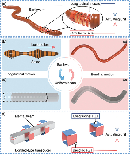
Figure 2. The design flow chart of two-DOF USM.
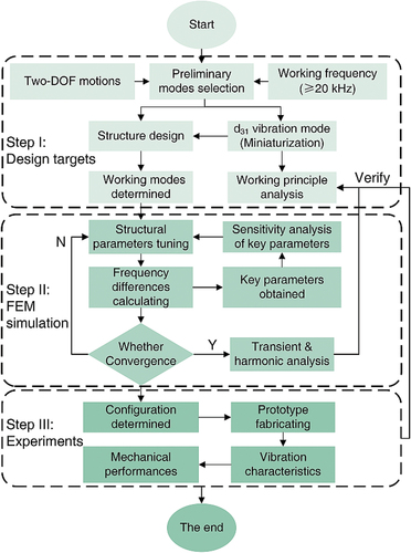
Figure 3. The metal substrate and the tentative working modes. (a) The structure of the cone-shaped horn substrate. (b) Adjustment of the resonant frequencies for the L2X and bending modes through changing the length of the metal substrate. (c) The second-order longitudinal mode. (d) Two orthogonal third-order modes. (e) Fifth-order and (f) seventh-order bending modes, respectively.
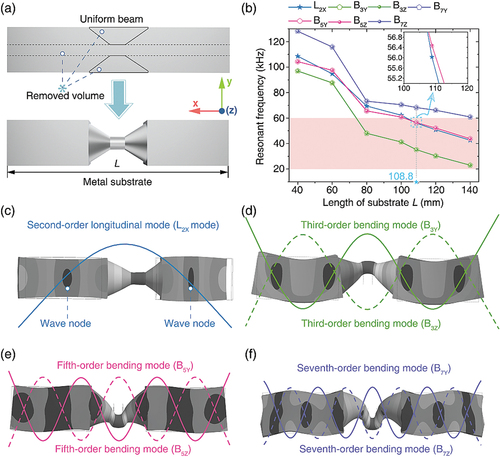
Figure 4. Configurations of the developed two-DOF BT.
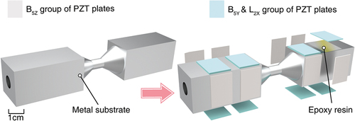
Figure 5. Schematic of exciting signals and desired working modes. (a) The exciting signals for two-DOF driving. (b) The electrical wiring diagram of B5Y mode, (c) B5Z mode, and (d) L2X mode.
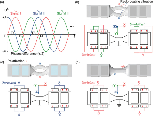
Figure 6. Schematic illustration of the working principle of two-DOF USM. (a) The linear motion of the proposed motor in one period. (b)The rotary motion of the proposed motor in one period.
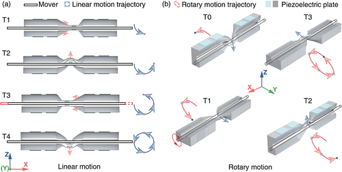
Figure 7. Influences of main geometric parameters of BT on B-B frequency. (a) Geometric dimensions of BT. (b) B-B frequency under different h2. (c) Resonant frequency under different d1, d2, and d3, where the decisive values are marked with light blue stars. (d) Resonant frequency under different h1.
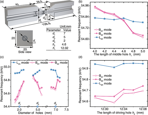
Figure 8. FEM results of the proposed two-DOF BT. (a) Three desired working modes. (b) The transient analysis results of motion trajectories of the driving surface (at steady state).
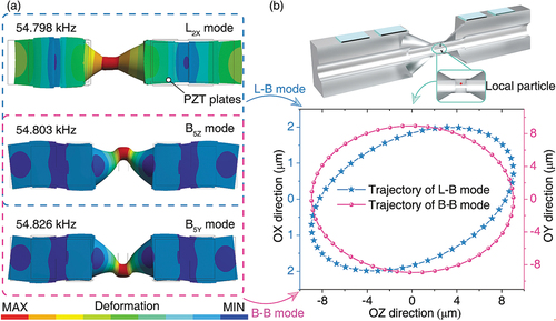
Figure 9. Fabrication, assembling process and weight distribution of fully assembled BT.
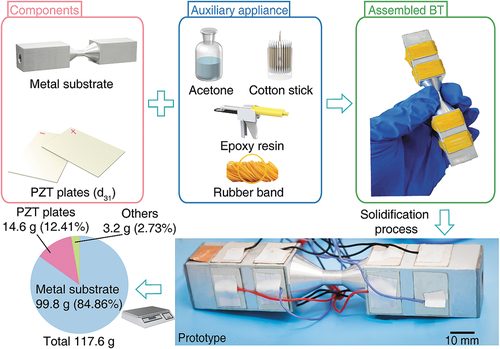
Figure 10. Testing results of vibration characteristics. (a) Schematic diagram of vibration test of the BT. (b) Vibration characteristics of the L2X mode. (c) Vibration characteristics of the B5Z mode. (d) Vibration characteristics of the B5Y mode.
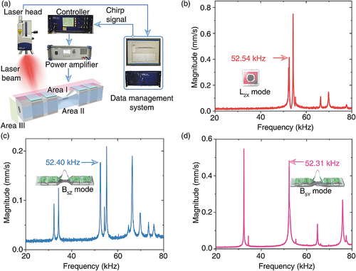
Figure 11. Experimental setup and results for USM’s speed measurement. (a) Experimental setup for two-DOF speed tests. (b) Frequency sensitivity results for the rotary and linear speeds of the mover.
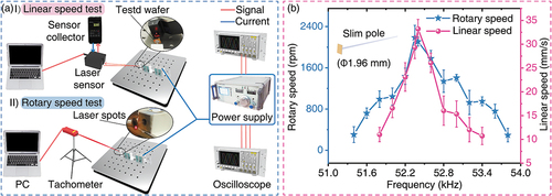
Figure 12. Relationships between the rotary and linear speeds and the voltage under no-load conditions.
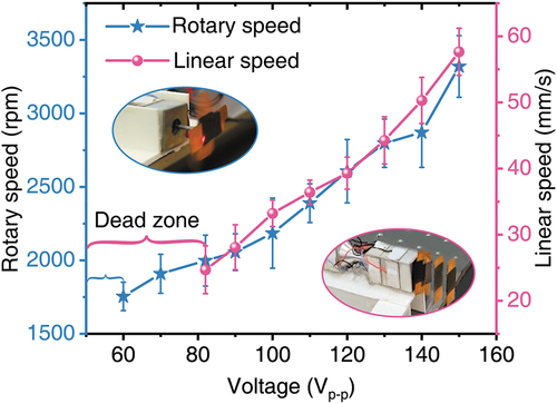
Figure 13. Experimental setup and results for USM’s load/torque measurement. (a) Experimental setups for two-DOF load tests. (b) Two-DOF speeds of prototype under different weights.
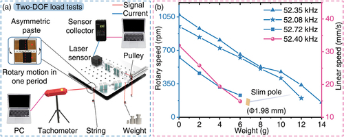
Figure 14. Transient response characteristics of linear motion.
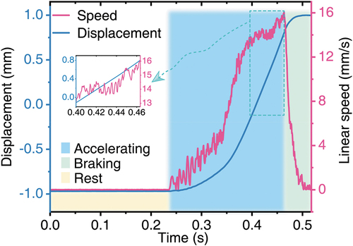
Table 1. Comparison of multi-DOF ultrasonic motors in recent years.
Figure 15. Relationships between the step displacements and the duty factor.
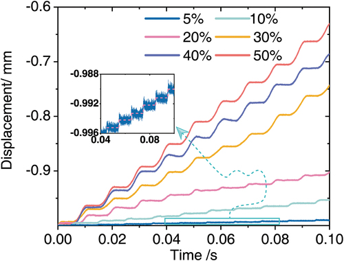
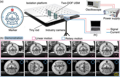
Figure 16. Demonstration of two-DOF motions. (a) Experimental setup for two-DOF motion tests. (b) The demonstration of two-DOF motions.