Figures & data
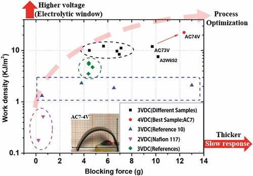
Figure 1. Strategy for realization of a large driving force in an IPMC actuator when approaching the performance of muscle.
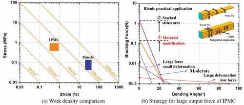
Figure 2. General fabrication process for the IPMC.
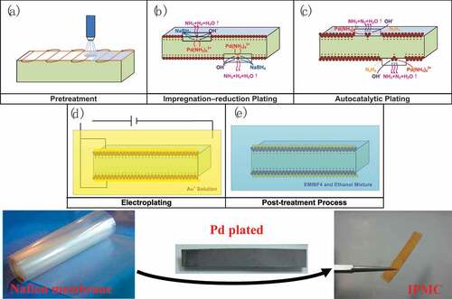
Figure 3. Illustration of isopropyl alcohol-assisted reduction plating steps.
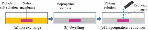
Figure 4. Silicon and PDMS molds for Nafion with a mesoscopic structure formed by hot pressing.
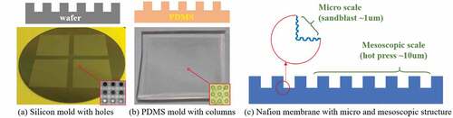
Figure 5. Layout of the Nafion membrane and the PDMS dies under the hot press.
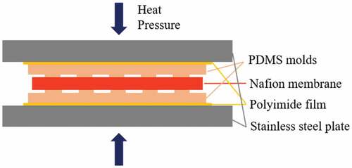
Figure 6. Illustration of (a) the IPMC performance test platform and (b) the test point when bending occurs.
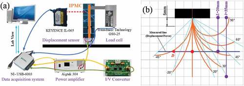
Figure 7. Cross-sectional scanning electron microscope (SEM) images of Nafion membranes with and without the doped CCNT particles. (a) 0% CCNT-Nafion. (b) 0.5% CCNT-Nafion. (c) 1% CCNT-Nafion. (d) 3% CCNT-Nafion. (e) 5% CCNT-Nafion.
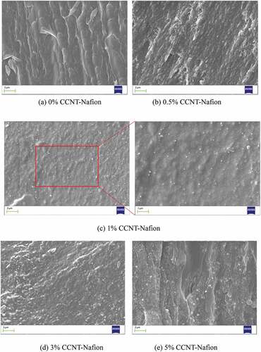
Figure 8. (a) Bending angles under 3 VDC application, and (b) blocking forces under 3 and 4 VDC application for IPMCs with various CCNT doping contents at a point located 20 mm away from the clamp.
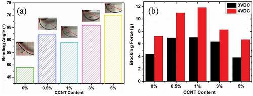
Figure 9. Displacements of IPMCs with various CCNT doping contents at a point located 20 mm away from the clamp under application of a square waveform voltage (3 V, 0.1 Hz).
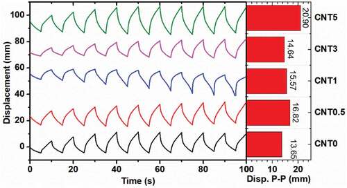
Table 1. Electromechanical properties of IPMCs with various CCNT doping contents.
Table 2. Experimental design of isopropyl alcohol-assisted reduction plating.
Figure 10. (a) Displacement under application of 3 VDC and (b) blocking force under application of 3 and 4 VDC of isopropyl alcohol-assisted plating IPMCs at a point located 20 mm away from the clamp.
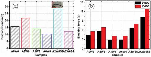
Figure 11. Displacement of isopropyl alcohol-assisted plating IPMCs at a point located 20 mm away from the clamp under application of a square waveform voltage (3 V, 0.1 Hz).
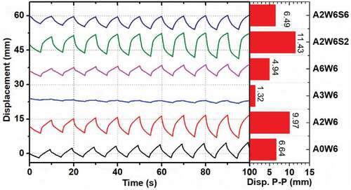
Figure 12. SEM images acquired at the electrode-polymer interface of the IPMCs without and with isopropyl alcohol-assisted plating.
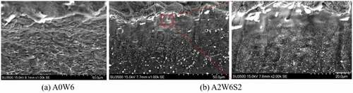
Table 3. Electromechanical properties of isopropyl alcohol-assisted plating IPMCs.
Figure 13. Surface morphology of hot-pressed Nafion membrane.
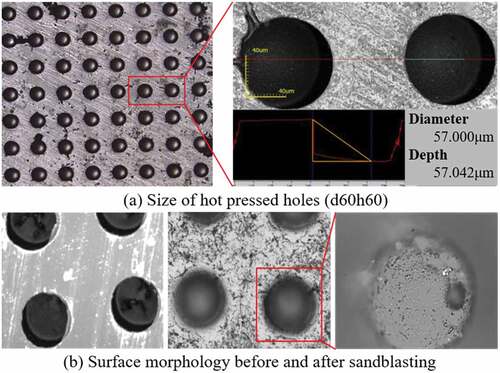
Figure 14. (a) Bending angles and (b) blocking forces under application of 3 VDC for various hot pressed IPMCs at a point located 20 mm away from the clamp.
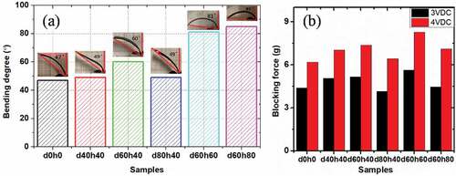
Figure 15. Displacement of various hot pressed IPMCs at a point located 20 mm away from the clamp under application of a square waveform voltage (3 V, 0.1 Hz).
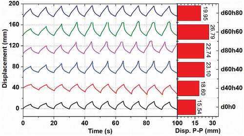
Table 4. Electromechanical properties of the hot-pressed IPMCs.
Table 5. Integration design of fabrication process with multiple optimized factors.
Figure 16. (a) Bending angles and (b) blocking forces under application of 3 VDC, and (c) displacement under application of a square waveform voltage (3 V, 0.1 Hz) for various hot-pressed IPMCs at a point located 20 mm away from the clamp.
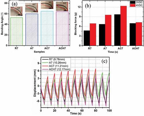
Table 6. Performance comparison of various IPMCs (35 mm × 5 mm, measured at L = 20 mm).
Figure 17. SEM images of CCNT-doped Nafion membrane without and with hot pressing.
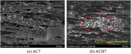
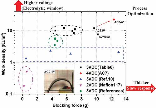
Figure 18. Summary of IPMC actuation performances and tendencies.