
Figures & data
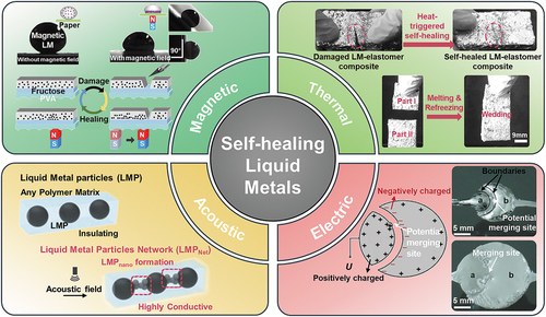
Table 1. Typical LMs with self-healing capabilities and their physical properties.
Figure 1. Three fundamental self-healing mechanisms for LMs. A. Droplet coalescence mechanism. Oscillating coalescence of two identical LM droplets in a NaOH solution. Reproduced with permission from ref [Citation30]. Copyright 2015, science china press. B. Volume expansion mechanism. (a) Schematic of the conductivity self-healing induced by volume expansion of LMs; (b) the distance between two LM droplets decreases due to their volume expansion. Reproduced with permission from ref [Citation31]. Copyright 2019, royal society of chemistry. C. Various binding of LM and its derivatives to chemical groups in polymers: (a) –OH [Citation32]; (b) –NH2 [Citation33]; (c) polysulfide loops (R–sn–R) and thiol terminal groups (R–SH) [Citation34]; (d) –COOH [Citation35]; (e) polyphenol [Citation36].
![Figure 1. Three fundamental self-healing mechanisms for LMs. A. Droplet coalescence mechanism. Oscillating coalescence of two identical LM droplets in a NaOH solution. Reproduced with permission from ref [Citation30]. Copyright 2015, science china press. B. Volume expansion mechanism. (a) Schematic of the conductivity self-healing induced by volume expansion of LMs; (b) the distance between two LM droplets decreases due to their volume expansion. Reproduced with permission from ref [Citation31]. Copyright 2019, royal society of chemistry. C. Various binding of LM and its derivatives to chemical groups in polymers: (a) –OH [Citation32]; (b) –NH2 [Citation33]; (c) polysulfide loops (R–sn–R) and thiol terminal groups (R–SH) [Citation34]; (d) –COOH [Citation35]; (e) polyphenol [Citation36].](/cms/asset/92492eb7-8fcf-4674-9863-054ef66f982b/tsnm_a_2385349_f0001_c.jpg)
Figure 2. Cases of mechanical stimulation induced droplet coalescence for self-healing of LMs. A. Schematic to illustrate the embossing process of discrete insulated LM microdroplets in elastomer matrix to form a connected conductive network. Reproduced with permission from ref [Citation47]. Copyright 2021, nature publishing group. B. SEM image to display local mechanical sintering of LM (EGaIn) nanoparticles. Detailed views highlight the formation of liquid EGaIn during pressing (top-right) and intact nanoparticles (bottom-right). Reproduced with permission from ref [Citation48]. Copyright 2015, Wiley-Blackwell. C. Schematic diagram of disconnection and reconnection of a basic electronic circuit using self-healing wire, where EGaIn is injected into microchannels fabricated with self-healing polymers. Reproduced with permission from ref [Citation49]. Copyright 2013, Wiley-Blackwell. D. Schematic diagram of self-healing LM line patterned on paper substrate. Reproduced with permission from ref [Citation50]. Copyright 2018, Wiley-Blackwell. E. Schematic detailing the self-healing flexible conductive LM/ITO film using a synergistic mechanism of mechanical stimulation and the spontaneous capillary-induced core suction of LM droplets. Reproduced with permission from ref [Citation6]. Copyright 2019, MDPI (Basel, Switzerland). F. Schematic illustrating a self-healing multilayer electrical circuit, where the LM flows are released from microcapsules to the damaged area upon encountering a crack. Reproduced with permission from ref [Citation51]. Copyright 2012, Wiley-Blackwell. G. Schematic diagram depicting an autonomously electrically self-healing LM – elastomer composite. Inset: equivalent electrical circuit schematic. Reproduced with permission from ref [Citation52]. Copyright 2018, Springer nature.
![Figure 2. Cases of mechanical stimulation induced droplet coalescence for self-healing of LMs. A. Schematic to illustrate the embossing process of discrete insulated LM microdroplets in elastomer matrix to form a connected conductive network. Reproduced with permission from ref [Citation47]. Copyright 2021, nature publishing group. B. SEM image to display local mechanical sintering of LM (EGaIn) nanoparticles. Detailed views highlight the formation of liquid EGaIn during pressing (top-right) and intact nanoparticles (bottom-right). Reproduced with permission from ref [Citation48]. Copyright 2015, Wiley-Blackwell. C. Schematic diagram of disconnection and reconnection of a basic electronic circuit using self-healing wire, where EGaIn is injected into microchannels fabricated with self-healing polymers. Reproduced with permission from ref [Citation49]. Copyright 2013, Wiley-Blackwell. D. Schematic diagram of self-healing LM line patterned on paper substrate. Reproduced with permission from ref [Citation50]. Copyright 2018, Wiley-Blackwell. E. Schematic detailing the self-healing flexible conductive LM/ITO film using a synergistic mechanism of mechanical stimulation and the spontaneous capillary-induced core suction of LM droplets. Reproduced with permission from ref [Citation6]. Copyright 2019, MDPI (Basel, Switzerland). F. Schematic illustrating a self-healing multilayer electrical circuit, where the LM flows are released from microcapsules to the damaged area upon encountering a crack. Reproduced with permission from ref [Citation51]. Copyright 2012, Wiley-Blackwell. G. Schematic diagram depicting an autonomously electrically self-healing LM – elastomer composite. Inset: equivalent electrical circuit schematic. Reproduced with permission from ref [Citation52]. Copyright 2018, Springer nature.](/cms/asset/ee6caeb4-ec28-4107-88aa-96bc9b14ca09/tsnm_a_2385349_f0002_c.jpg)
Figure 3. Four remote stimulation induced droplet coalescence for self-healing of LMs. A. Magnetic field induced self-healing: (a) photographs depicting contact angle before and after applying magnetic field and obliquity tests with magnetic field) of LM on paper; (b) schematic illustrating the healing mechanism of Fe-EGaIn electronics facilitated via magnetic field. (a) and (b) reproduced with permission from ref [Citation57]. And ref [Citation59], respectively. Copyright 2019, Wiley-VCH Verlag. B. Thermal field induced self-healing: photographs depicting the heat-triggered self-healing for LM-elastomer composite. Reproduced with permission from ref [Citation61]. Copyright 2016, Wiley-Blackwell. C. Acoustic field induced self-healing: schematic demonstrating the synthesis of highly conductive LM nanoparticles network in acoustic field. Reproduced with permission from ref [Citation62]. Copyright 2022, American association for the advancement of science. D. Electric field induced self-healing: In-plane self-healing capability of LM electrodes induced by electrostatic attraction forces at boundaries. Reproduced with permission from ref [Citation63]. Copyright 2013, American Institute of Physics.
![Figure 3. Four remote stimulation induced droplet coalescence for self-healing of LMs. A. Magnetic field induced self-healing: (a) photographs depicting contact angle before and after applying magnetic field and obliquity tests with magnetic field) of LM on paper; (b) schematic illustrating the healing mechanism of Fe-EGaIn electronics facilitated via magnetic field. (a) and (b) reproduced with permission from ref [Citation57]. And ref [Citation59], respectively. Copyright 2019, Wiley-VCH Verlag. B. Thermal field induced self-healing: photographs depicting the heat-triggered self-healing for LM-elastomer composite. Reproduced with permission from ref [Citation61]. Copyright 2016, Wiley-Blackwell. C. Acoustic field induced self-healing: schematic demonstrating the synthesis of highly conductive LM nanoparticles network in acoustic field. Reproduced with permission from ref [Citation62]. Copyright 2022, American association for the advancement of science. D. Electric field induced self-healing: In-plane self-healing capability of LM electrodes induced by electrostatic attraction forces at boundaries. Reproduced with permission from ref [Citation63]. Copyright 2013, American Institute of Physics.](/cms/asset/0746d6b3-79da-47b5-8509-a6f2e1319c91/tsnm_a_2385349_f0003_c.jpg)
Figure 4. Phase transition induced reversible self-healing. A. Insulation and conduction transition of a LM-polymer composite triggered by the phase change of LM droplets and the rigidity change of polymer. Reproduced with permission from ref [Citation73]. Copyright 2019, Wiley-Blackwell. B. Schematic of solidified LM droplets expanding and connecting with adjacent ones. Reproduced with permission from ref [Citation74]. Copyright 2020, Elsevier BV. C. Temperature tunable conductor-insulator transition of a LM-polymer composite. D. Differential scanning calorimeter tests reveal an exothermic peak at 227 K that signifies the transition of liquid LM nanoparticles. C and D were produced with permission from ref [Citation31]. Copyright 2019, royal society of Chemistry.
![Figure 4. Phase transition induced reversible self-healing. A. Insulation and conduction transition of a LM-polymer composite triggered by the phase change of LM droplets and the rigidity change of polymer. Reproduced with permission from ref [Citation73]. Copyright 2019, Wiley-Blackwell. B. Schematic of solidified LM droplets expanding and connecting with adjacent ones. Reproduced with permission from ref [Citation74]. Copyright 2020, Elsevier BV. C. Temperature tunable conductor-insulator transition of a LM-polymer composite. D. Differential scanning calorimeter tests reveal an exothermic peak at 227 K that signifies the transition of liquid LM nanoparticles. C and D were produced with permission from ref [Citation31]. Copyright 2019, royal society of Chemistry.](/cms/asset/d4a91de9-3503-43b0-99ed-e421c82ad330/tsnm_a_2385349_f0004_c.jpg)
Figure 5. Chemical crosslinking enabled self-healing in LM composites. A. Schematic of chemical crosslinking serving as sutures to achieve wound self-healing in LM composites. Reproduced with permission from ref [Citation80]. Copyright 2022, Elsevier. B. Self-healing scheme for LM-embedded sulfur polymer materials. Reproduced with permission from ref [Citation34]. Copyright 2019, Wiley-VCH Verlag. C. Design strategy (a) and self-healing mechanism (b) of supramolecular PAA – LM/rGO hydrogels. Reproduced with permission from ref [Citation35]. Copyright 2021, royal society of chemistry. D. Formation and reversible self-healing of PVA-LMPs hydrogel. Reproduced with permission from ref [Citation81]. Copyright 2019, American chemical society. E. Scheme illustrating the self-healing mechanism of magnetic PVA/EGaInSn–Ni hydrogel. Reproduced with permission from ref [Citation58]. Copyright 2023, Springer Singapore.
![Figure 5. Chemical crosslinking enabled self-healing in LM composites. A. Schematic of chemical crosslinking serving as sutures to achieve wound self-healing in LM composites. Reproduced with permission from ref [Citation80]. Copyright 2022, Elsevier. B. Self-healing scheme for LM-embedded sulfur polymer materials. Reproduced with permission from ref [Citation34]. Copyright 2019, Wiley-VCH Verlag. C. Design strategy (a) and self-healing mechanism (b) of supramolecular PAA – LM/rGO hydrogels. Reproduced with permission from ref [Citation35]. Copyright 2021, royal society of chemistry. D. Formation and reversible self-healing of PVA-LMPs hydrogel. Reproduced with permission from ref [Citation81]. Copyright 2019, American chemical society. E. Scheme illustrating the self-healing mechanism of magnetic PVA/EGaInSn–Ni hydrogel. Reproduced with permission from ref [Citation58]. Copyright 2023, Springer Singapore.](/cms/asset/1a2e7784-bf6b-4e7c-b255-360e8921ad74/tsnm_a_2385349_f0005_c.jpg)
Table 2. Comparison of self-healing strategies for liquid metals.
Figure 6. Examples of LM wearable devices with self-healing functions. A. Clothes with integrated multiple sensors (top). Textile fibers containing LM (bottom). Top left image: reproduced with permission from ref [Citation92]. Copyright 2022, American Chemical Society. Top right image: reproduced with permission from ref [Citation93]. Copyright 2019, American Chemical Society. Bottom image: reproduced with permission from ref [Citation94]. Copyright 2023, Elsevier BV. B. LM-based exoskeleton fixator for joint protection. Reproduced with permission from ref [Citation95]. Copyright 2023, Wiley-VCH Verlag. C. Schematic of real-time EEG recording during sleep state. Reproduced with permission from ref [Citation96]. Copyright 2022, American Chemical Society. D. Images of a glove equipped with LM capacitive sensor network and EMG signal acquisition using LM electronic tattoo on the forearm. Reproduced with permission from ref [Citation97]. Copyright 2018, American Chemical Society. E. Palisade shape stretchable LM@PDMS heater for thermotherapy at knee. Reproduced with permission from ref [Citation98]. Copyright 2019, Wiley-Blackwell.
![Figure 6. Examples of LM wearable devices with self-healing functions. A. Clothes with integrated multiple sensors (top). Textile fibers containing LM (bottom). Top left image: reproduced with permission from ref [Citation92]. Copyright 2022, American Chemical Society. Top right image: reproduced with permission from ref [Citation93]. Copyright 2019, American Chemical Society. Bottom image: reproduced with permission from ref [Citation94]. Copyright 2023, Elsevier BV. B. LM-based exoskeleton fixator for joint protection. Reproduced with permission from ref [Citation95]. Copyright 2023, Wiley-VCH Verlag. C. Schematic of real-time EEG recording during sleep state. Reproduced with permission from ref [Citation96]. Copyright 2022, American Chemical Society. D. Images of a glove equipped with LM capacitive sensor network and EMG signal acquisition using LM electronic tattoo on the forearm. Reproduced with permission from ref [Citation97]. Copyright 2018, American Chemical Society. E. Palisade shape stretchable LM@PDMS heater for thermotherapy at knee. Reproduced with permission from ref [Citation98]. Copyright 2019, Wiley-Blackwell.](/cms/asset/65c93471-e0af-44a5-84e1-10e0d05a1545/tsnm_a_2385349_f0006_c.jpg)
Figure 7. Application of LM in self-healing battery electrodes. A. Synthesis procedure of a room-temperature self-healing anode for lithium-ion batteries with Ga-sn LM alloy stabilizing in a reduced graphene oxide/carbon nanotube skeleton. Reproduced with permission from ref [Citation106]. Copyright 2017, royal society of chemistry. B. Schemes of spontaneous repairing LM/Si anode for lithium-ion battery. (a) Charge-discharge process of the LM/Si anode (left); (b) STEM image (right-top) and element mappings of LM/Si anodes before (right-middle) and after (right-bottom) discharge. Reproduced with permission from ref [Citation107]. Copyright 2018, Elsevier BV. C. Carbonization steps and electrochemical processes of self-healing LM nanoparticles encapsulated in hollow carbon fibers as a free-standing anode for lithium-ion batteries. Reproduced with permission from ref [Citation108]. Copyright 2019, Elsevier BV. D. Hollow Ga2O3@N-CQD as a self-healing anode for lithium-ion batteries. Reproduced with permission from ref [Citation109]. Copyright 2020, American Chemical society.
![Figure 7. Application of LM in self-healing battery electrodes. A. Synthesis procedure of a room-temperature self-healing anode for lithium-ion batteries with Ga-sn LM alloy stabilizing in a reduced graphene oxide/carbon nanotube skeleton. Reproduced with permission from ref [Citation106]. Copyright 2017, royal society of chemistry. B. Schemes of spontaneous repairing LM/Si anode for lithium-ion battery. (a) Charge-discharge process of the LM/Si anode (left); (b) STEM image (right-top) and element mappings of LM/Si anodes before (right-middle) and after (right-bottom) discharge. Reproduced with permission from ref [Citation107]. Copyright 2018, Elsevier BV. C. Carbonization steps and electrochemical processes of self-healing LM nanoparticles encapsulated in hollow carbon fibers as a free-standing anode for lithium-ion batteries. Reproduced with permission from ref [Citation108]. Copyright 2019, Elsevier BV. D. Hollow Ga2O3@N-CQD as a self-healing anode for lithium-ion batteries. Reproduced with permission from ref [Citation109]. Copyright 2020, American Chemical society.](/cms/asset/03978ee3-887b-4ec0-b33d-8a295b9e8eec/tsnm_a_2385349_f0007_c.jpg)
Figure 8. Self-healing design using LMs in soft robotics. A. Structure of the soft robotic with autonomously self-healing soft electronics (left); the soft robot encountering puncture damage from a hole punch traverses smooth terrain without altering its gait, requiring no manual intervention or external energy sources to continue moving (right). Reproduced with permission from ref [Citation52]. Copyright 2018, Springer Nature. B. The activation of the self-healing LMPA substrate results in a bending shape of VSEDA. Reproduced with permission from ref [Citation131]. Copyright 2015, IEEE/RSJ. C. (a) Object grasping analysis: resistance changes during hand movements and sequential pressure application (top). Sensor positions on the index finger, thumb, and palm (bottom); (b) assembly of layers, LM injection, and formation of electrical contacts with Ag NW sticker. (a) Reproduced with permission from ref [Citation132]. Copyright 2016, RSC. (b) Reproduced with permission from ref [Citation133]. Copyright 2015, Wiley-VCH Verlag. D. Representative photos depict LMESP-50% composite bone specimens during self-healing tests. After being cut in half, the specimens were left to self-heal under ambient conditions. The images below offer detailed views of the cut samples. Reproduced with permission from ref [Citation34]. Copyright 2019, Wiley-VCH.
![Figure 8. Self-healing design using LMs in soft robotics. A. Structure of the soft robotic with autonomously self-healing soft electronics (left); the soft robot encountering puncture damage from a hole punch traverses smooth terrain without altering its gait, requiring no manual intervention or external energy sources to continue moving (right). Reproduced with permission from ref [Citation52]. Copyright 2018, Springer Nature. B. The activation of the self-healing LMPA substrate results in a bending shape of VSEDA. Reproduced with permission from ref [Citation131]. Copyright 2015, IEEE/RSJ. C. (a) Object grasping analysis: resistance changes during hand movements and sequential pressure application (top). Sensor positions on the index finger, thumb, and palm (bottom); (b) assembly of layers, LM injection, and formation of electrical contacts with Ag NW sticker. (a) Reproduced with permission from ref [Citation132]. Copyright 2016, RSC. (b) Reproduced with permission from ref [Citation133]. Copyright 2015, Wiley-VCH Verlag. D. Representative photos depict LMESP-50% composite bone specimens during self-healing tests. After being cut in half, the specimens were left to self-heal under ambient conditions. The images below offer detailed views of the cut samples. Reproduced with permission from ref [Citation34]. Copyright 2019, Wiley-VCH.](/cms/asset/f69913d1-d544-4099-b572-149eb00a9bcd/tsnm_a_2385349_f0008_c.jpg)