3,921
Views
14
CrossRef citations to date
0
Altmetric
Articles

Nanoindentation in elastoplastic materials: insights from numerical simulations

, &
Pages 95-114 | Received 08 Dec 2009, Accepted 19 Jan 2010, Published online: 09 Apr 2010

Figures & data

Table 1. Evolution of yield stress with plastic strain

Figure 1. (Color online). Comparison of experimentally obtained stress–strain curves with the simulation of a combined isotropic/kinematic hardening plasticity model.
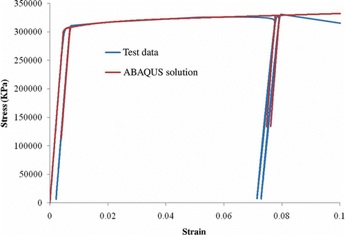
Figure 1. (Color online). Comparison of experimentally obtained stress–strain curves with the simulation of a combined isotropic/kinematic hardening plasticity model.

Figure 2. Face partitioning of 2D axisymmetric specimen.

Figure 2. Face partitioning of 2D axisymmetric specimen.

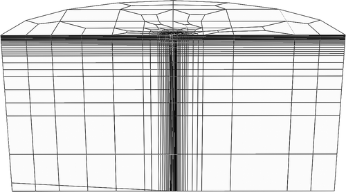
Figure 3. 2D axisymmetric finite element mesh of the specimen.

Figure 3. 2D axisymmetric finite element mesh of the specimen.

Figure 4. (Color online). Load–displacement comparison for elastic indentation simulation into a specimen with r s = 18 μm and h s = 30 μm.
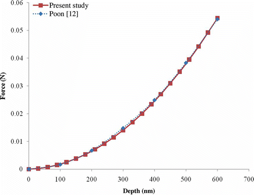
Figure 4. (Color online). Load–displacement comparison for elastic indentation simulation into a specimen with r s = 18 μm and h s = 30 μm.

Figure 5. (Color online). Load–displacement comparison for elastic indentation simulation into a specimen with varying indenter tip radii, ρ (30, 705, 120, 150 and 200 nm).
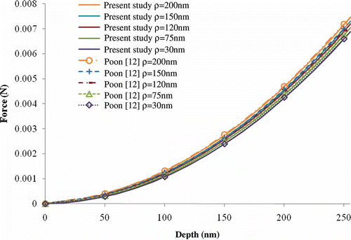
Figure 5. (Color online). Load–displacement comparison for elastic indentation simulation into a specimen with varying indenter tip radii, ρ (30, 705, 120, 150 and 200 nm).

Figure 6. (Color online). Load–displacement curves for elastic indentation simulation into a specimen with r s = 18 μm and varying h s (18, 30, 42, 60, 92 and 120 μm).
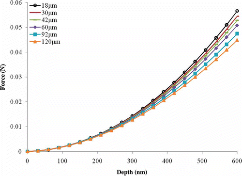
Figure 6. (Color online). Load–displacement curves for elastic indentation simulation into a specimen with r s = 18 μm and varying h s (18, 30, 42, 60, 92 and 120 μm).

Figure 7. (Color online). Comparison of the simulations using different 2D axisymmetric finite element meshes in elastoplastic indentation.
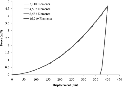
Figure 7. (Color online). Comparison of the simulations using different 2D axisymmetric finite element meshes in elastoplastic indentation.

Figure 8. 3D finite element mesh of the specimen.

Figure 8. 3D finite element mesh of the specimen.

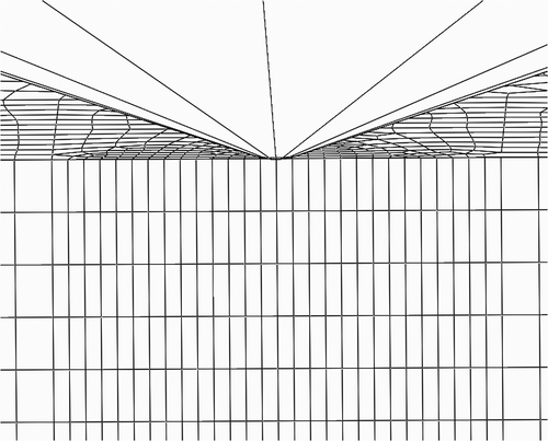
Figure 9. Local details of 3D finite element mesh near the indenter.

Figure 9. Local details of 3D finite element mesh near the indenter.

Figure 10. Local top surface details of the modified 3D finite element mesh configured to improve interaction with Berkovich indenter.
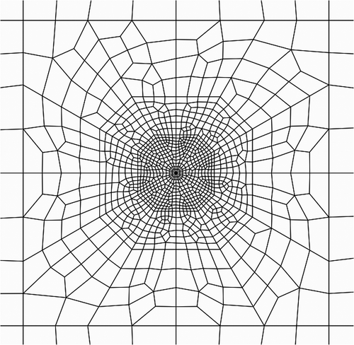
Figure 10. Local top surface details of the modified 3D finite element mesh configured to improve interaction with Berkovich indenter.

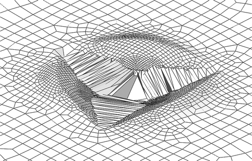
Figure 11. Mesh distortion observed in explicit simulation of Berkovich indentation.

Figure 11. Mesh distortion observed in explicit simulation of Berkovich indentation.

Figure 12. (Color online). Comparison of load–displacement curves for 2D and 3D conical indentations.
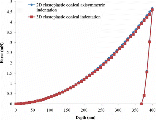
Figure 12. (Color online). Comparison of load–displacement curves for 2D and 3D conical indentations.

Figure 13. (Color online). Comparison of load–displacement curves for conical and Berkovich indentations.
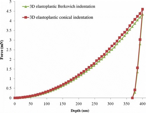
Figure 13. (Color online). Comparison of load–displacement curves for conical and Berkovich indentations.

Figure 14. (Color online). Comparison of contact areas computed in conical and Berkovich indentations.
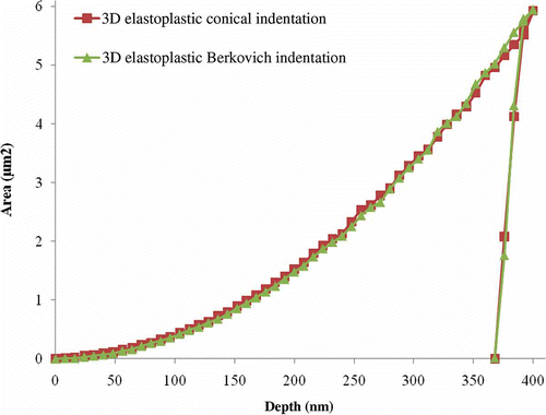
Figure 14. (Color online). Comparison of contact areas computed in conical and Berkovich indentations.

Figure 15. (Color online). Comparison of normalized contact stresses computed for conical and Berkovich indentations.
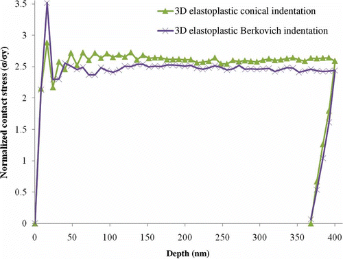
Figure 15. (Color online). Comparison of normalized contact stresses computed for conical and Berkovich indentations.

Figure 16. (Color online). Mises stress for (a) 70.3° conical indenter, (b) Berkovich indenter, viewed in plane perpendicular to indenter edge, and (c) Berkovich indenter, viewed in plane of indenter edge. (Figure continued).
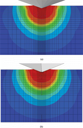
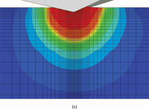
Figure 16. (Color online). Mises stress for (a) 70.3° conical indenter, (b) Berkovich indenter, viewed in plane perpendicular to indenter edge, and (c) Berkovich indenter, viewed in plane of indenter edge. (Figure continued).
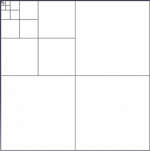
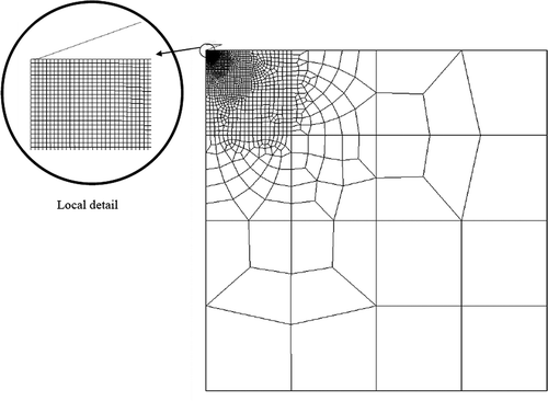
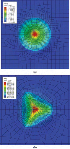
Figure 17. (Color online). Contours of equivalent plastic strain for (a) 70.3° conical indenter and (b) Berkovich indenter.

Figure 17. (Color online). Contours of equivalent plastic strain for (a) 70.3° conical indenter and (b) Berkovich indenter.

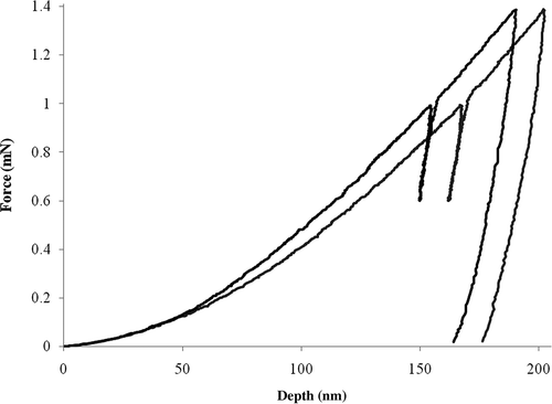
Figure 18. Upper and lower bounds of experimental load–displacement curves.

Figure 18. Upper and lower bounds of experimental load–displacement curves.

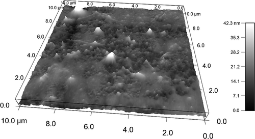
Figure 19. AFM-produced contour plot of specimen surface.

Figure 19. AFM-produced contour plot of specimen surface.

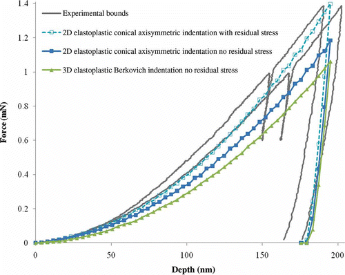
Figure 20. (Color online). Comparison of numerically obtained force–displacement curves with experimental bounds.

Figure 20. (Color online). Comparison of numerically obtained force–displacement curves with experimental bounds.

Reprints and Corporate Permissions

Please note: Selecting permissions does not provide access to the full text of the article, please see our help page How do I view content?

To request a reprint or corporate permissions for this article, please click on the relevant link below:

Academic Permissions

Please note: Selecting permissions does not provide access to the full text of the article, please see our help page How do I view content?

Obtain permissions instantly via Rightslink by clicking on the button below:

If you are unable to obtain permissions via Rightslink, please complete and submit this Permissions form. For more information, please visit our Permissions help page.